The usage model explains the use of the command and control system and which processes are involved. It entails operation overviews, collaborations, use cases and scenario descriptions:
Single button operations
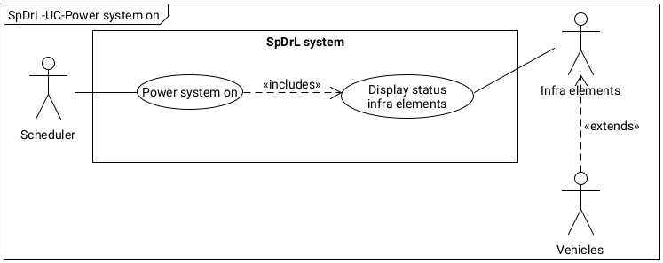
Resetting systemRTN pressed
The software executes a system wide reset by pressing RTN for 5 seconds.
A reset is also invoked when the system is switched on.
RTN
Ortsnetzrücksteltaste
Use case diagram main power with actions and conditions.
Change luminosity indicationVHT, EHT pressed
The software reduces the illumination intensity of the SpDrL60 indication when VHT is pressed and increases it when EHT is pressed.
EHT
Erhöhen Helligkeit Taste
VHT
Verringern Helligkeit Taste
Select cab numberZAT pressed
The software performs the assignment of the next cabin unit by means of a traction selection controller when ZAT is pressed.
ZAT
Zugnummerauswahltaste
Single infra element operations
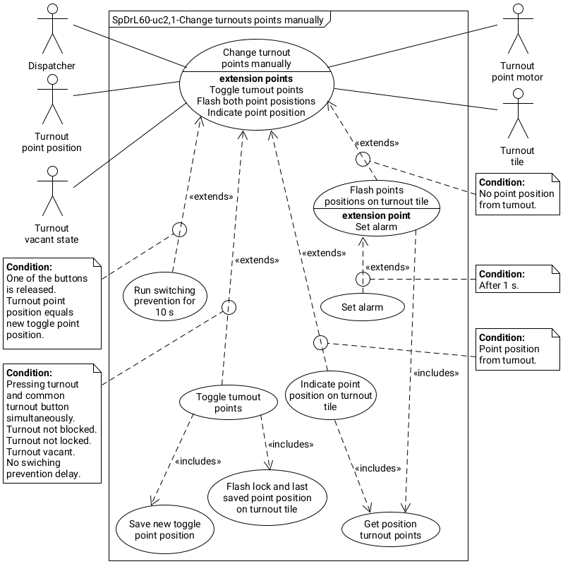
Change turnouts manuallyWT+WGT pressed
The software executes the switchover of points by pressing the WT on the turnout tile and the WGT simultaneously.
Precondition is that:
the turnout is reported vacant
the turnout is not blocked
the turnout is not locked
switching prevention delay (10s) not is active.
WT
Weichentaste
WGT
Weichengruppentaste
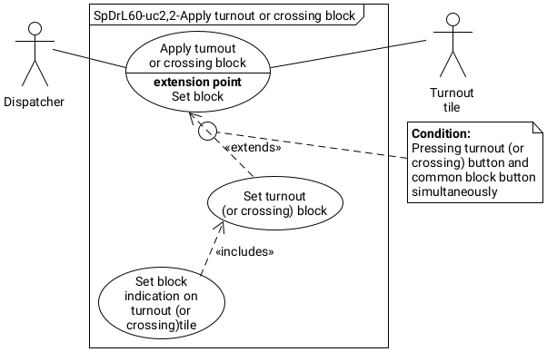
Apply turnout or crossing blockWT+SpT pressed
The software executes the application of a block on a turnout or crossing by pressing the WT on the turnout or crossing tile and the SpT simultaneously. The block is indicated by a continuous red light in the block indicator
The block of a remotely controlled turnout prevents:
the points of the turnout from being switched
routes from being set via the unlit lights of the turnout.
Precondition:
None
WT
Weichentaste
SpT
Sperrtaste
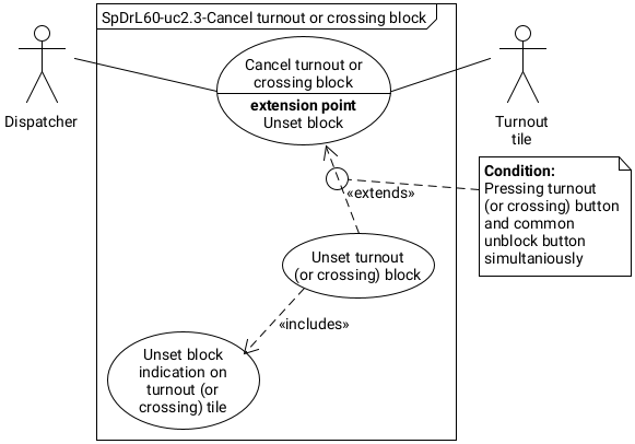
Cancel turnout or crossing blockWT+ESpT pressed
The software executes the cancellation of a block of a turnout or crossing by pressing the WT on the turnout or crossing tile and the ESpT simultaneously . The block indicator goes off.
Precondition:
None.
WT
Weichentaste
ESpT
Entsperrtaste
Apply block main signalZST+SpT pressed
The software executes the application of a block on a main signal by pressing the ZST on the main signal tile and the SpT simultaneously. An entry signal cannot be blocked. A block is indicated by a continuous red light in the block indicator.
Precondition is that:
the signal is at danger
no route is set
ZST
Zugstartfahrstraßentaste
SpT
Sperrtaste
Cancel block main signalZST+ESpT pressed
The software executes the cancellation of the block of a main signal by pressing the ZST on the main signal tile and the ESpT simultaneously. Note that a block cannot be apply entry signals.
Precondition:
None.
ZST
Zugstartfahrstraßentaste
ESpT
Entsperrtaste
Apply block shunting signalVST+SpT pressed
The software executes the application of a block on a shunting signal by pressing the VST on the shunting signal tile and SpT simultaneously. The block is indicated by a continuous red light in the block indicator.
Precondition is that:
the signal is at danger
no route is set
VST
Verschubstartfahrstraßentaste
SpT
Sperrtaste
Cancel block shunting signalVST+ESpT pressed
The software executes the cancellation of a block on a shunting signal by pressing the VST on the shunting signal tile and the ESpT simultaneously. The block indicator goes off.
Precondition:
None.
VST
Verschubstartfahrstraßentaste
ESpT
Entsperrtaste
Apply destination block main routeZZT+SpT pressed
The software executes the application of a block of a main route to a destination signal by pressing the ZZT on the main signal tile and SpT simultaneously. The block is indicated by a continuous red light in the block indicator of the main signal.
Precondition:
None.
ZZT
Zugzielfahrstraßentaste
SpT
Sperrtaste
Cancel destination block main routeZZT+ESpT pressed
The software executes the cancellation of a block of a main route to a destination signal by pressing the ZZT on the main signal tile and ESpT simultaneously. The block indicator of the main signal goes off.
The software executes the application of a block of a shunting route to a destination signal by pressing the VZT on the shunting signal tile and the SpT simultaneously. The block is indicated by a continuous red light in the block indicator.
The software executes the cancellation of a block of a shunting route to a destination signal by pressing the VZT on the shunting signal tile and the ESpT simultaneously. The block indicator goes off.
Precondition:
None.
VZT
Verschubzielfahrstraßentaste
ESpT
Entsperrtaste
Set proceed on sightZST+ErsGT pressed
The software executes the activation of a “proceed on sight” signal at a signal by pressing the ZST on the main or intermediate signal tile and the ErsGT simultaneously. After the “proceed on sight” signal lights up, the stop indicator goes off.
Precondition is that:
no key malfunction occurs.
ZST
Zugstartfahrstraßentaste
ErsGT
Ersatzsignalgruppentaste
Cancel proceed on sightZST+HaGT pressed
The software executes the cancellation of “proceed on sight” signal at a signal by pressing the ZST on the main or intermediate signal tile and the HaGT simultaneously. The “proceed on sight” signal light goes off.
Precondition:
None.
ZST
Zugstartfahrstraßentaste
HaGT
Haltgruppentaste
Cancel at danger for non vacant sectionZST+SGT pressed
The software executes the cancellation of the aspect at danger of an signal by pressing the SGT on the intermediate signal tile and the ZST simultaneously.
The at danger signal light goes off.
This applies only to signals which divide a single track in blocks e.g. at platforms and running tracks.
Precondition is that:
the signal is not blocked and the adjacent block section is not reported non-vacant.
ZST
Zugstartfahrstraßentaste
SGT
Signalgruppentaste
Cancel protective pathZST+FSRT pressed
The software executes the cancellation of a protective path of the set route by pressing the ZZT on the main signal tile and the FSRT simultaneously. The cancellation of the protective path is recognisable by the extinguishing of the lock indication of the turnouts and the track non vacant indicator in the protective path and the target triangle.
Precondition is that:
when the route has already been released (white flashing light in the target triangle)
the station track is still non vacant.
ZST
Zugzielfahrstraßentaste
FSRT
Schutzwegrücknahmetaste
Couple traction vehiclesKGT+VST pressed
The software executes the Isolation of the traction section with a traction vehicle by pressing the VST on the shunting tile and the KGT simultaneously.
Precondition is that:
when a shunting route is set towards the section with a stationary traction vehicle to be coupled.
KGT
Kuppelunggruppetaste
VST
Verschubstartfahrstraßentaste
Uncouple traction vehiclesEGT+VZT pressed
The software executes the isolation of the traction section with a traction vehicle and activate the uncoupler at the track by pressing the VZT on the shunting tile and the EGT simultaneously.
Precondition:
when a shunting route is set from the section with a stationary traction vehicle to be uncoupled.
EGT
Entkuppelunggruppetaste
VZT
Verschubzielfahrstraßentaste
Route operations
from this point onward.
Main route settingZST+ZZT pressed
Main route setting is achieved if the following buttons are pressed simultaneously:
Route from an entry signal: The start button ZST and the destination button ZZT of the main signal, an intermediate or an exit signal tile.
From an exit signal or intermediate signal: The main signal button ZST and the destination button ZZT on the exit signal.
ZST
Zugstartfahrstraßentaste
ZZT
Zugzielfahrstraßentaste
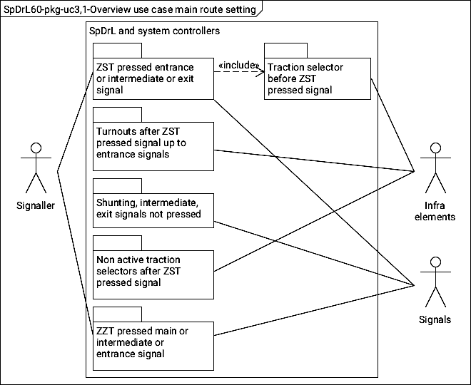
Overview use case of the control system components for main route setting.
When the ZST and ZZT buttons are pressed simultaneously the following simplified actions take place:
Route from an entry signal: The entry signal control component shall send a 'request main route message' with the cab number stored in the traction selector before this entry signal. The intermediate or the exit signal shall send a 'set main route' message with the aspect of the signal on arrival at the simultaneously pressed button ZZT.
From an exit signal or intermediate signal: The exit signal control component shall send a 'request main route' message with the cab number stored in the traction selector before this exit signal. The intermediate or the entry signal shall send a 'set main route' message with the aspect of the signal on arrival the at the tile with simultaneously pressed button ZZT.
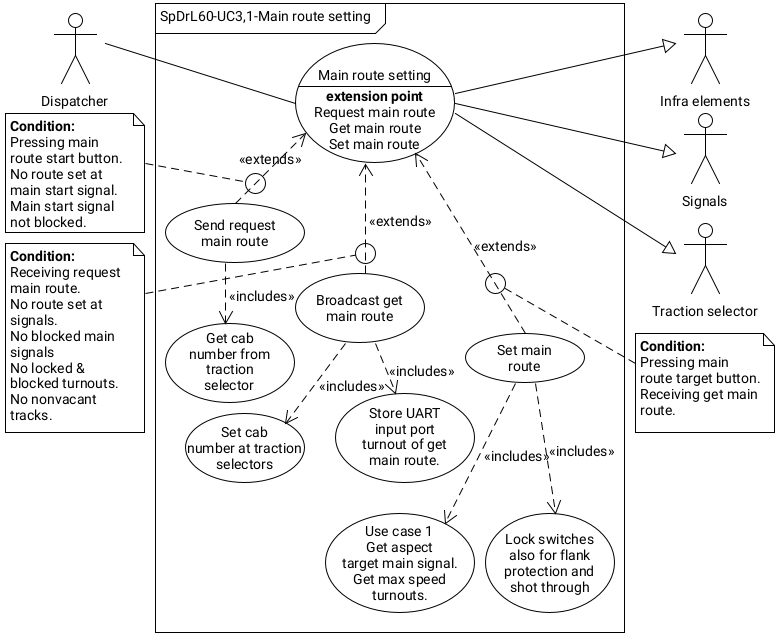
Use case diagram main route setting with actions and conditions.
Use case 'Main route setting' are stated in the table below.
Main route setting use case scenario.
Use case:
Set main route.
Use case no.:
SpDrL60-UC 3.1
Revision date:
2023-03-26
Revision no.:
001
Description:
Short description of the scenario.
Priority customer:
Roelf Koerts.
Primary actor:
Left lolly stick of initiating user in this use case diagram.
Secondary actors:
Left and right lolly sticks of include, extend and secondary users in use case diagram.
Preconditions:
The main signal of the button pressed shall not be blocked.
Result:
Success:
The direct result of a successful completion of this use case.
Failure:
The direct result of a unsuccessful completion of this use case.
Post conditions:
Points are set and locked, in between cab selectors are set, the aspect and direction arrow starting signal is set and locked..
Limitations:
A main route from a intermediate signal to an exit or intermediate signal is not allowed.
Assumptions:
The designation signal is here the entrance signal where a destination button is pressed or a second main button is pressed at a intermediate or exit signal
Trigger:
Main start button pressed of entry signal or main button pressed on intermediate or exit signal.
Main scenario:
1. Get cab number from first cab selector at front of the start signal.
2. Send message form the start signal in the direction passing this signal with request for main route and obtained cab number.
3. On receiving the main route requist massage at the designation signal a lock message is send with a set lock command and aspect of the main signal.
4. On receiving the lock message at the start signal the aspect and direction arrow is set.
Extensions:
2.1 - The condition to divert form the main scenario
2.1.1 - Description step 2.2
Source:
N/A
Author:
Roelf Koerts
Checked by:
...
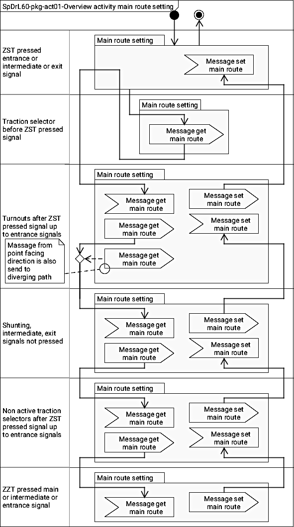
Package activity diagram met overview of the actions 'Set main route':
Shunting route settingVST+VZT pressed
Shunting route setting is achieved on pressing the following buttons simultaneously:
From a shunting or intermediate signal to another similar signal: The shunting button on the starting tile and the shunting button on destination shunting, intermediate or exit signal tile.
From shunting or intermediate signal to a shunting termination: The signal button on the starting tile and the destination key on the to (nach) button tile.
VST
Verschubstartfahrstraßentaste
VZT
Verschubzielfahrstraßentaste
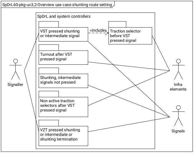
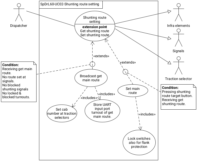
Overview use case of the control system components to set a shunting route.
When the VST and VZT buttons are pressed simultaneously the following simplified actions take place:
From a shunting or intermediate signal to another similar signal: The signal control component with the pressed VST sends a 'request shunting route' message with the cab number stored in the traction selector before this signal. The shunting or intermediate signal sends a 'set shunting route' message on arrival of the 'request shunting route' message at the simultaneously pressed button ZZT.
From shunting or intermediate signal to a shunting termination: The shunting or intermediate signal VST pressed control component sends a 'request main route' message with the cab number stored in the traction selector before this signal. The shunting termination component sends a 'set main route' message on arrival of the 'request shunting route' message at the tile with simultaneously pressed button ZZT.
Use case diagram shunting route setting with actions and conditions.
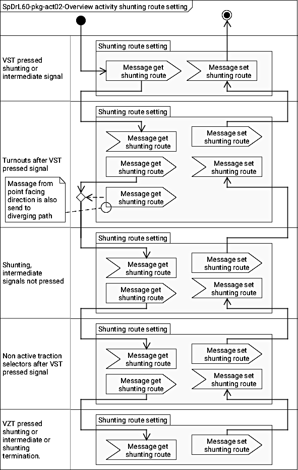
Package activity diagram met overview of the actions 'set shunting route':
Main route releasingTrain detection
Parts of main route is released by traction sections connected to a traction selector:
If a vehicle enters that traction section.
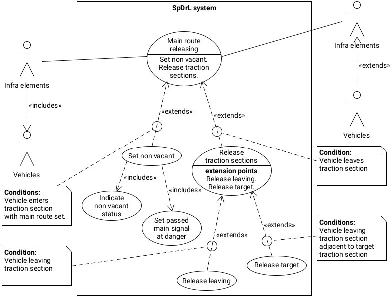
Overview use case of the control system components for 'main route releasing':
When a vehicle enters a traction section of a set route the following actions take place:
The route release of that that part of the route including the infra elements and signals.
The traction control from the cab unit remains until the section is vacant to allow for uninterrupted current and supply to trains with more than one self propelled vehicle of a self propelled vehicle at the rear of the train.
Use case diagram shunting route setting with actions and conditions.
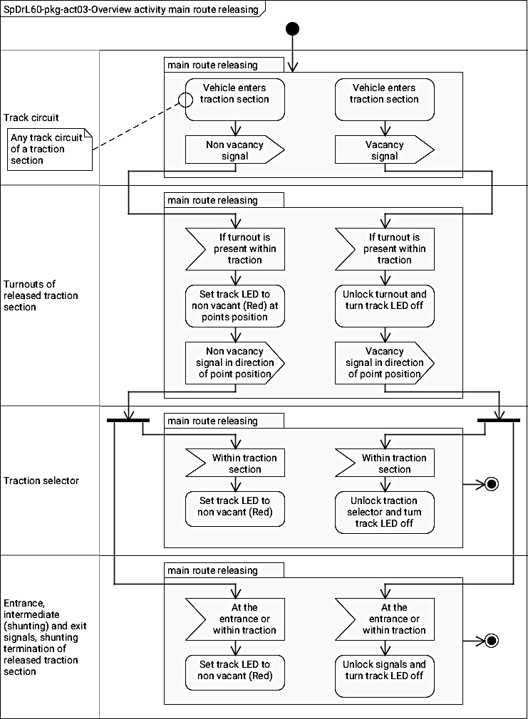
Package activity diagram met overview of the actions 'automatic route release':
Shunting route releasingTrain detection
Parts of shunting route is released by traction sections connected to a traction selector:
If a vehicle enters that traction section.
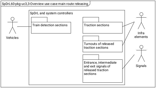
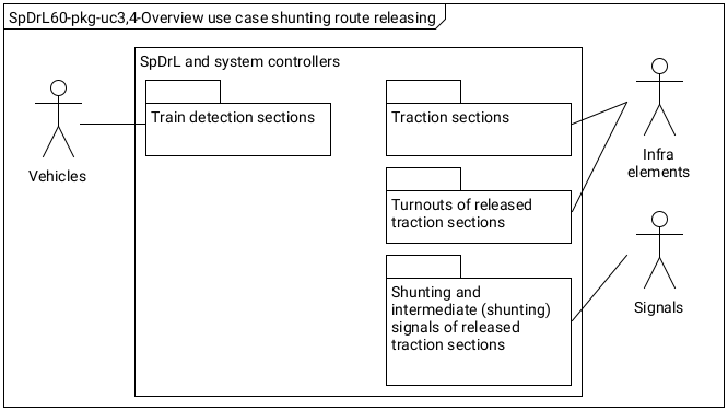
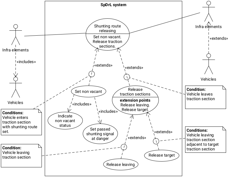
Overview use case of the control system components for 'shunting route releasing':
Use case diagram shunting route releasing with actions and conditions.
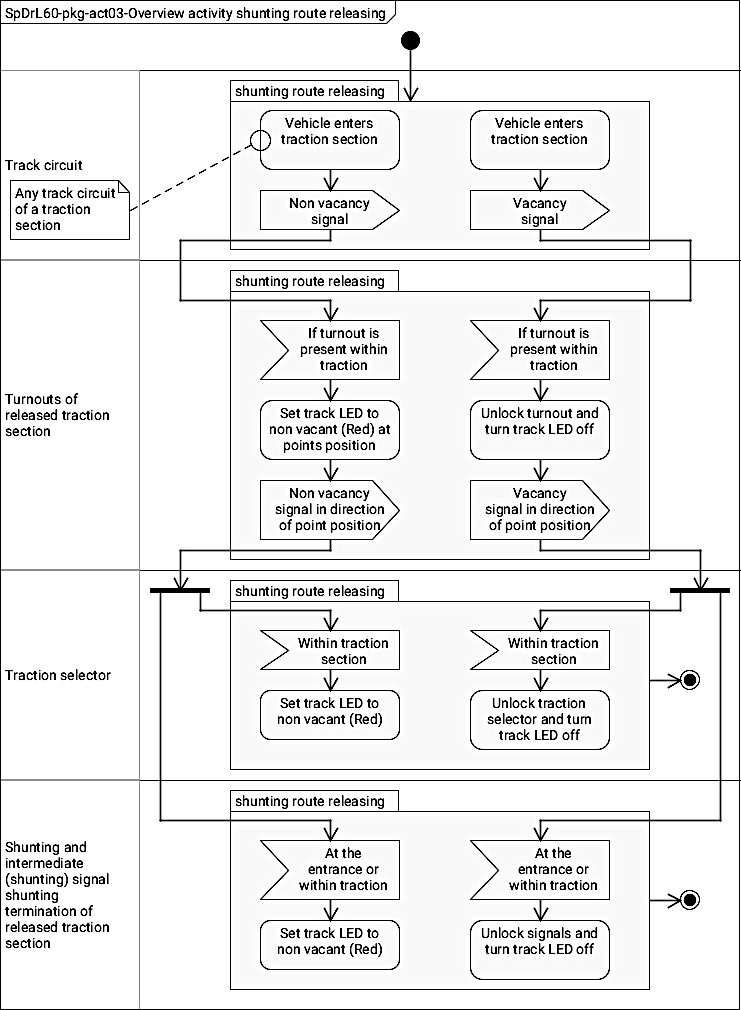
Overview activity, shunting route releasing.
Main route cancellingZZT+FRT pressed
The software executes ...
ZZT
Zugzielfahrstraßentaste
FRT
Fahrstraßenrücknahmetaste
Overview use case of the control system components for 'main route cancelling':
Figure SpDrL60 pkg-uc
When a FRT and ZZT buttons are pressed simultaneously the following simplified actions takes place:
Route to a exit or intermediate: The exit or intermediate signal control of the target signal shall send a 'cancel main route' message in the direction of the signal control component of the start signal. The message chain will stop at the traction selector which is already released.
Route to an entrance signal: The entrance signal control component of the target signal shall send a 'cancel main route' message in the direction of the signal control component of the start signal. The message chain will stop at the traction selector which is already released.
Package activity diagram met overview of the actions 'main route releasing':
Figure spdrl60-pks-act
Shunting route cancellingVZT+FRT pressed
The software executes ...
VZT
Verschubzielfahrstraßentaste
FRT
Fahrstraßenrücknahmetaste
Overview use case of the control system components for 'shunting route cancelling':


 from this point onward.