This webpage is about the properties of physical nodes used for designing, testing, selecting materials to build the controls for my model railway. It consists of the topics:
Command panel
This chapter is about the physical aspects of the SpDrL60 mosaic command panel like the construction, making the tiles and PCB for the tiles.
Common controls and indicators
Breakout PCBCommon tiles
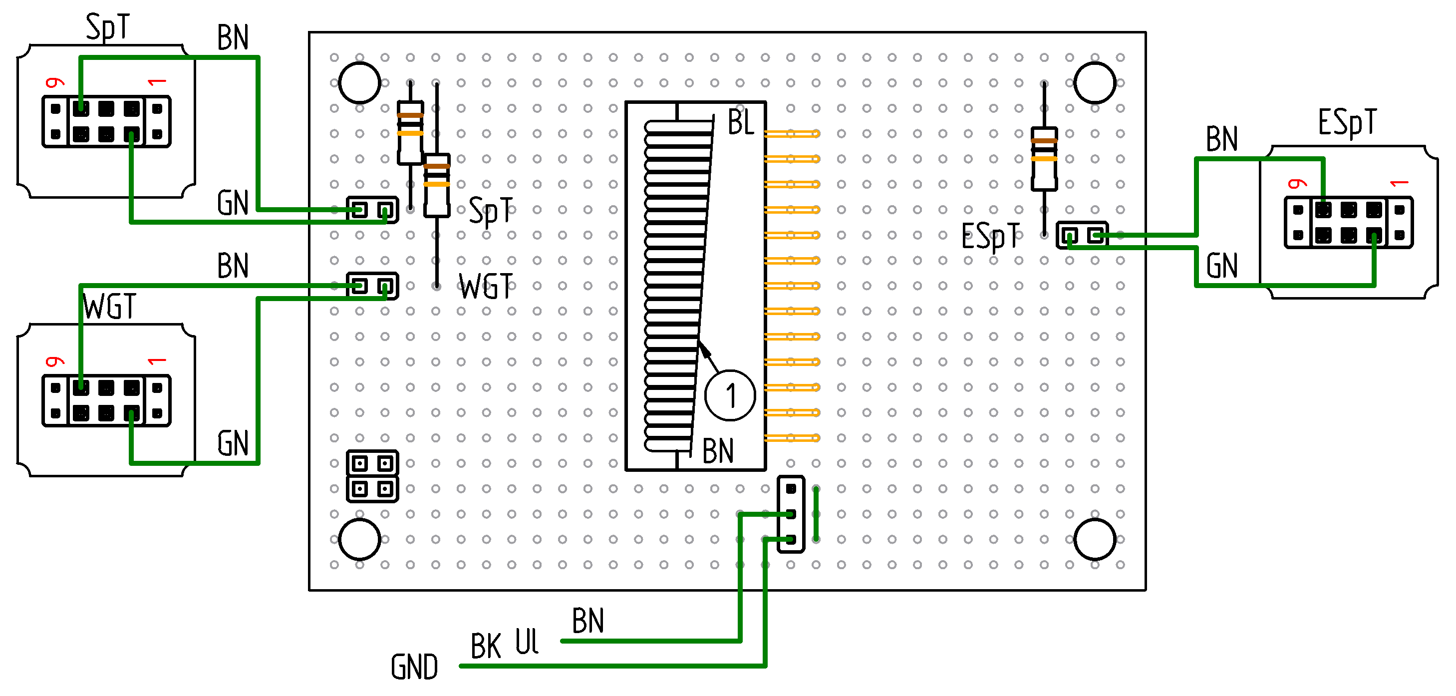
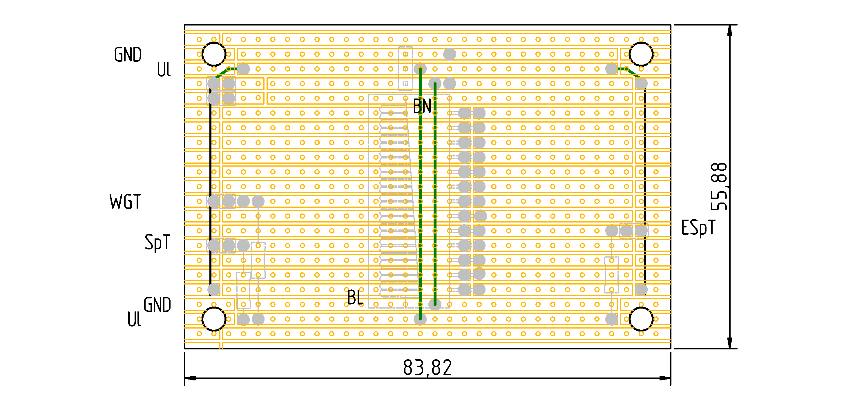
The common breakout board is connected to the power supply circuit board in 19-inch racks via an 26-core ribbon cable. This allows the common tiles to be connected. At present, this applies exclusively to tiles with WGT, SpT and ESpT. These are connected in this way to the the turnout controller PCBs. Dupont connectors are used to connect single wires.
Stranded wires are used when there are Dupont connectors at both ends of the wires.
Flexible wiring 0.14 mm² Outer diameter 1.2 mm Green
Merktronics Art.No.: 7010M
Current rating 1.5A
5 m
Control unit
This chapter is about the physical aspects of the 19 inch and other sub trays including the PCB's with control circuitry, power PCB, and other PCB's.
Electronic components of the system controller shall be located on PCBs in 19 inch trays, due to the lack of space behind the SpDrL panel. Common connections will run on the back plane and individual connections with plugs on the front of the Eurocards.
Command and control wiring
This chapter contains the sections on the wiring from the PCBs containing the control and detection circuits to the mosaic tiles, the tracks and the point motors.
Wire end identification
The following convention is used to indicate the location of a terminal to which a particular wire end is connected:
When it is located on a printed circuit board in a tray
The capital letter of that tray, i.e. A, B, C, etc.
The two-digit number of the position within that tray, i.e. 01, 02, 03, etc.
When it is located on a stand-alone PCB
The number of that PCB, i.e. 1, 2, 3, etc.
The label at a terminal, for example on a printed circuit board, is preceded by a hyphen and is designated as follows:
The number of a circuit if it appears more than once on a PCB, i.e. 1, 2, 3, etc.
The unique abbreviation for the required or provided function of a terminal, beginning with an uppercase or lowercase letter, e.g. GND for earth, Ul for logic voltage, Pt for the control power used to set and monitor a through route of a turnout
A sequence number if there is more than one terminal with the same required or provided function
Examples for identifying the location of a terminal:
D03-1Pt
Tray D, slot 03
-
Terminal label 1Pt, i.e. Pt of circuit 1
A15-R1t
Tray A, slot 15
-
Terminal label R1t
1-WGT
Standalone PCB 1
-
Terminal label WGT
PSU1-Ul
Power supply 1
-
Terminal label Ul
See the Structure web page for the meaning of the printed labels at terminals.
Wires and cables from turnout controllers
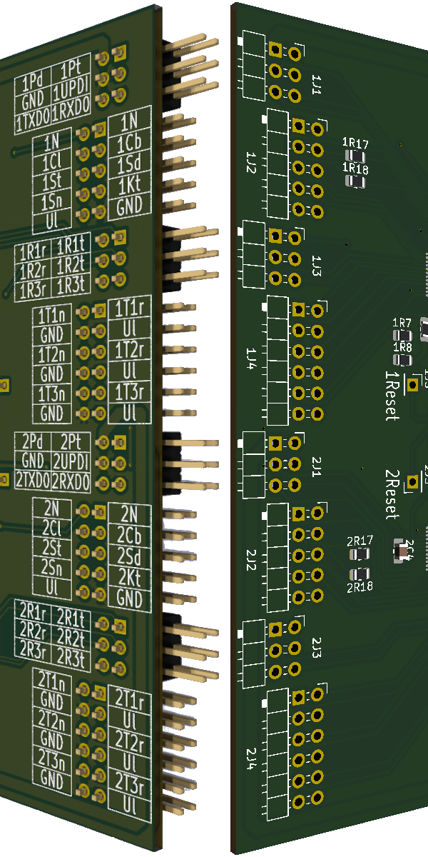
This section deals with the cabling and the wiring from the turnout controllers in the 19-inch racks. Below are the names of the pin headers and pins of the turnout controller PCBs.
The first number of the header and pin names are replaced by the letter n in the drawings of the turnout controller connections below.
Stranded core wire is used if connected to a Dupont crimp connector. This is required to ensure a reliable connection also at low currents.
Turnout controller header nJ1Point motor and UPDI programmer
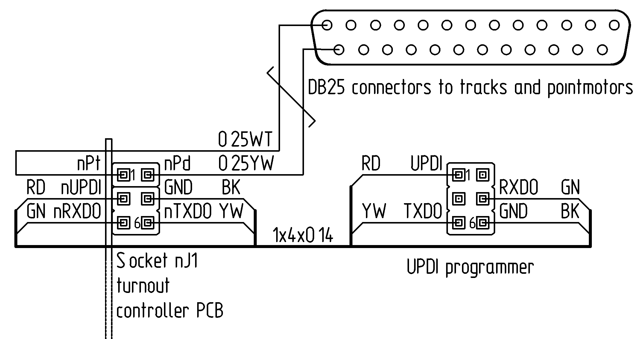
Connections from header nJ1 of the turnout controller:
to a point motor with wires to a DB25 connector, from this connector multi core cables are running to point motors and tracks
to a UPDI programmer with a cable which is only present when programming a microcontroller on the turnout controller PCB.
For the control and indication of the points, the pin designations and corresponding wire IDs are as follows:
nPt
pointT
The control voltage for a point motor the set the points in the through direction
nPd
pointD
The control voltage for a point motor the set the points in the diverge direction
The soldered wires to for example DB-25 D-subminature connectors are solid core to avoid breakage. In this case, the Dupont connectors are also soldered to the other end.
ID
Component
Properties
Qty
pointT
Single solid core wire 0.20 mm². Outer diameter 0.7 mm White
Okaphone Elektronika Art.No.: MD040WT
Current rating 5.0A
100m
pointD
Single solid core wire 0.20 mm². Outer diameter 0.7 mm Yellow
Okaphone Elektronika Art.No.: MD040GE
Current rating 5.0A
100m
Turnout controller header nJ2Turnout tile and train detector
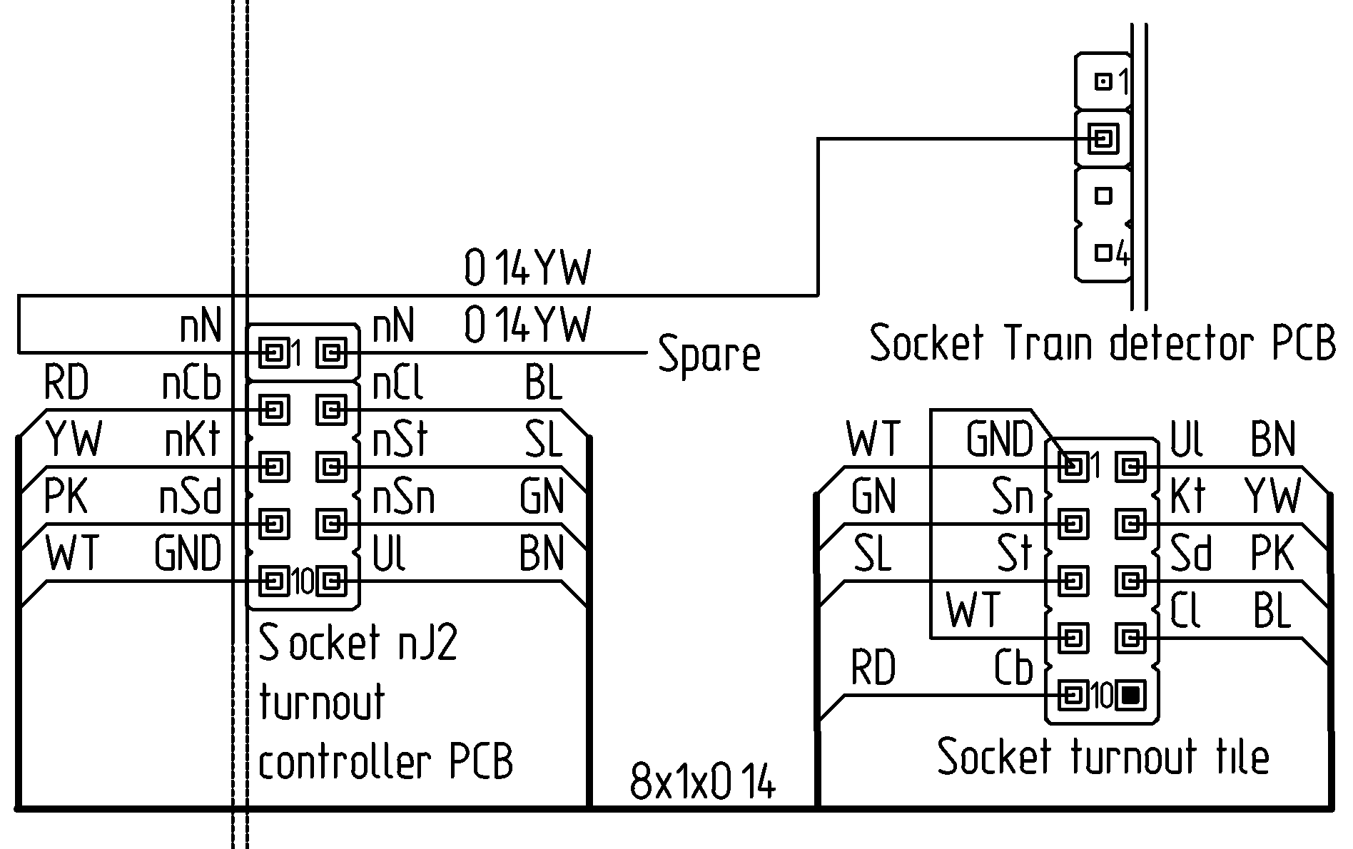
Each connection from the header nJ2 of the turnout controller to the turnout points tile of the mosaic control panel consist of a stranded 8-core cable with Dupont connectors at each end. The cable type and the connectors are shown below.
The connection to a train detector PCB consist of a stranded wire with Dupont connectors at each end. The spare wire is may be used to daisy chain the output from the train detector PCB to other controllers.
Component
Properties
Qty
TiYY cable with eight stranded cores of 0.14 mm². Outer diameter 4.9 mm Slate Unittronic Art.No.: 0028208
Current rating 1.5A
120m
Turnout controller header nJ3Serial data connection
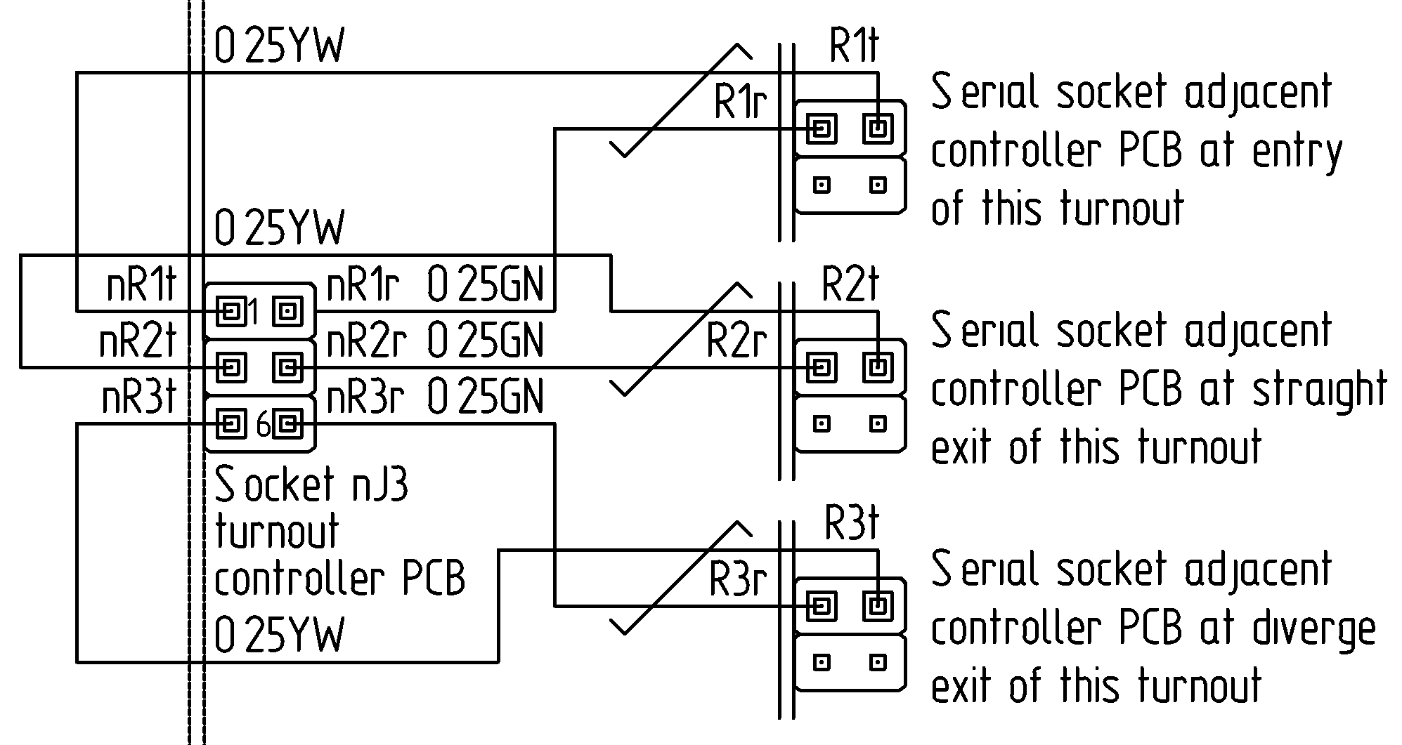
The serial data connection from the header nJ3 of the turnout controller to adjacent controllers of this turnout consist of two twisted stranded wires with Dupont connectors at each end.
Turnout controller header nJ4Adjacent status tiles
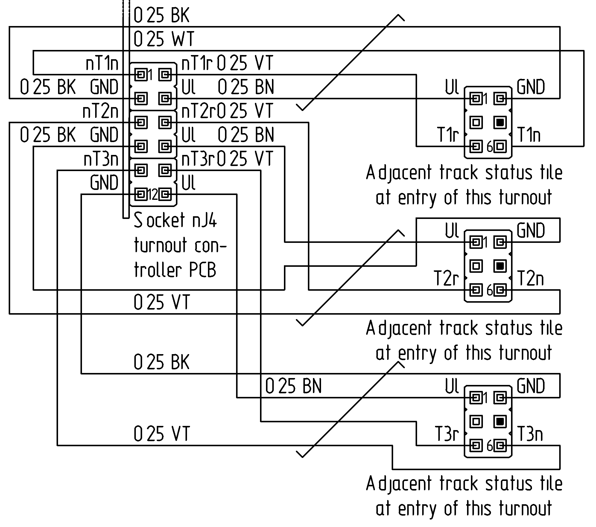
The connection from the header nJ4 of the turnout controller to adjacent tile to turnout tile in question on the mosaic panel consist of four twisted stranded wires with Dupont connectors at each end. Connections are omitted if these adjacent tiles on the mosaic panel do not require a track states provided by this turnout controller.
Wires and cables from traction controllers
This section covers the wiring from the printed circuit boards containing traction controllers in 19-inch racks to the DB 25 connectors behind the mosaic panel, which are connected to the track sections and the turnout motors.
The wire colours and their designation are:
SL
railT
The traction voltage for a traction rail section
GN
railD
The return voltage for a train detection rail section
The soldered wires to for example DB-25 D-subminature connectors are solid core to avoid breakage. All other wires connected to the Dupont connectors of the PCB's in sub racks are stranded. This ensures a reliable connection to the Dupont crimp pins especially with low-currents. The wires have enough over length to remove the connections and trace the wires.
ID
Component
Properties
Qty
railT
Single solid core wire 0.50 mm². Outer diameter 1.4 mm Slate
Okaphone Elektronika Art.No.: MD08GS
Current rating 6.0A
100m
railD
Single solid core wire 0.50 mm². Outer diameter 1.4 mm Green
Okaphone Elektronika Art.No.: MD08GN
Current rating 6.0A
200m
Signal wiring
This chapter is about the physical aspects of the communication of I2C for line side signals.