The model describes behavioural aspects of the command and control system. At present, this is an incomplete draft that will be amended as development progresses.
The contents of the this web page is as follows:
Bits route messages
This section covers the bits used in message interactions of the route setting interface. The route massage is a half-duplex serial interface and is 11 bits long. The layout is:
Start bit
Message bits
Parity bit
End bit
s
7
6
5
4
3
2
1
0
p
e
Common abbreviations used in the paragraphs below:
x
Means N/A
Message bit 0 ≤ 1
Bit 0 ≤ 1 indicates the route action.
Bit 1
Bit 0
Re message
a1
a0
All
Designation of bits:
an
Route action. The two letters stand for the route commands:
a1
a0
Route action
0
0
None
0
1
Get route
1
0
Set route
1
1
Release route
Message bit 2
Bit 2 is allocated to the type of route where the the action is for.
Bit 2
Re message
t
All
Designation of bit:
t
Route type. The letter stands for the route type:
t
Route type
0
Main route
1
Shunting route
Message bit 3 ≤ 6
The allocation for bit 3 ≤ 6 is depends on the message. For the massage to get a main route it is to communicate to which cab unit (train ID) the route should be connected for traction. For the message to set a main route it is to communicate the signal aspects at the beginning of the route depending of the position of turnouts along the route and the signal aspect at the end of the route. For the other messages the bits are ignored.
Train ID. The bit value 0x0 is a request to return the driver’s cab unit number (TrainID) set in the associated traction selection controller. The bit value 0x0 ≤ 0xF represents to which driver’s cab unit the route tracks should be connected to. This allows to drive 15 trains on the layout. It is ignored if the route type is for shunting.
mn
Main signal aspect. The two letters represent the aspects of main signals at the start of a main route, see below.
dn
Distant signal aspect. The two letters represent the aspects of distant signals at the start of the route, see below.
Main signal aspects:
m1
m0
Main signal aspect
0
0
No restriction
0
1
60 kmh restriction
1
0
40 kmh restriction
1
1
At danger
Distant signal aspects:
d1
d0
Distant signal aspect
0
0
Expect no restriction
0
1
Expect 60 kmh restriction
1
0
Expect 40 kmh restriction
1
1
Expect at danger
Message bit 7
Bit 7 is used to set the polarity on the tracks in the return loops.
Bit 7
Re message
r
getMainRoute in return loops
x
All the others
Designation of bit:
r
Reversed polarity. The letter stands for the reversed polarity of the marshalling tracks. This is required for return loops.
r
Polarity
0
No polarity change
1
Reverse polarity
Route interactions
Main route setting interactionsZST+ZZT pressed
The collaboration diagrams, below shows the communication between components to achieve a main route settings.
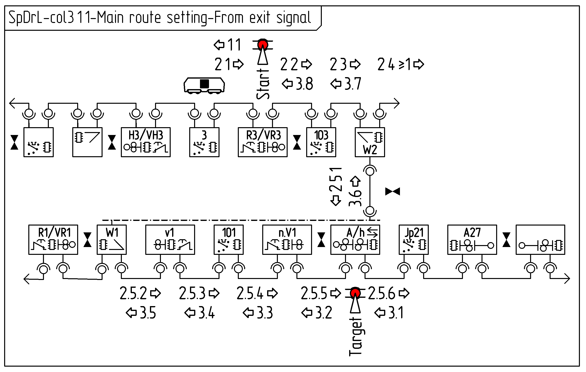
The first diagram covers main route setting between an entrance signal and an exit signal. The messages and purpose of them between the components are:
getMainRoute: Obtain CabNo
getMainRoute: Check if route is clear. Deliver CabNo to traction selectors. Set target point route at turnouts.
setMainRoute: Set route status at main signals. Obtain aspect target main signal. Enable traction at traction selectors. Lock turnouts. Obtain lowest maximum speed of points. Set aspect at start distance and main signal.
The diagrams below shows the communication between components to achieve this main route setting.
Message 1: getMainRoute
Component
Prerequisite
Action
Component
Prerequisite
Action
R3
ZST pressed (Start). Not blocked. Not locked.
VR3
Not blocked. Not locked.
Send message 1.
Massage reference: 1.1 ⇦
3
Destination message 1.
Message 2: getMainRoute
Component
Prerequisite
Action
Component
Prerequisite
Action
3
Not vacant. Cab number is set.
Add Cab number to message 2. Send message 2.
Massage reference: 2.1 ⇨
VR3
Not locked.
R3
Not blocked. Not locked.
Pass message 2 through.
Massage reference: 2.2 ⇨
103
Vacant. Not locked
Enable traction from Cab number in massage 2. Pass message 2 through.
Massage reference: 2.3 ⇨
W2
Vacant. Not locked. Not blocked.
Add maximum speed to message 2 for both directions. Send message 2 in both directions.
Massage reference: 2.4 ⇨ and 2.5.1 ⇩
W1
Vacant. Not locked. Not blocked.
Store direction message 2 came from. Add maximum speed to message 2. Send message 2.
Massage reference: 2.5.2 ⇨
v1
Not locked. Not blocked.
Pass message 2 through.
Massage reference: 2.5.3 ⇨
101
Vacant. Not locked
Enable traction from Cab number in massage 2. Pass message 2 through
Massage reference: 2.5.4 ⇨
n.V1
Not locked
Pass message 2 through
Massage reference: 2.5.5 ⇨
h
A
ZZT pressed (Target). Vacant. Not blocked. Not locked.
Pass message 2 through.
Massage reference: 2.5.6 ⇨
Jp21
Destination message 2.
Message 3: setMainRoute
Component
Prerequisite
Action
Component
Prerequisite
Action
The last automatic block, here Jp21
Vacant. Not Locked
Enable traction from Cab number in massage 2. Send message 3.
Massage reference: 3.1 ⇦
…
…
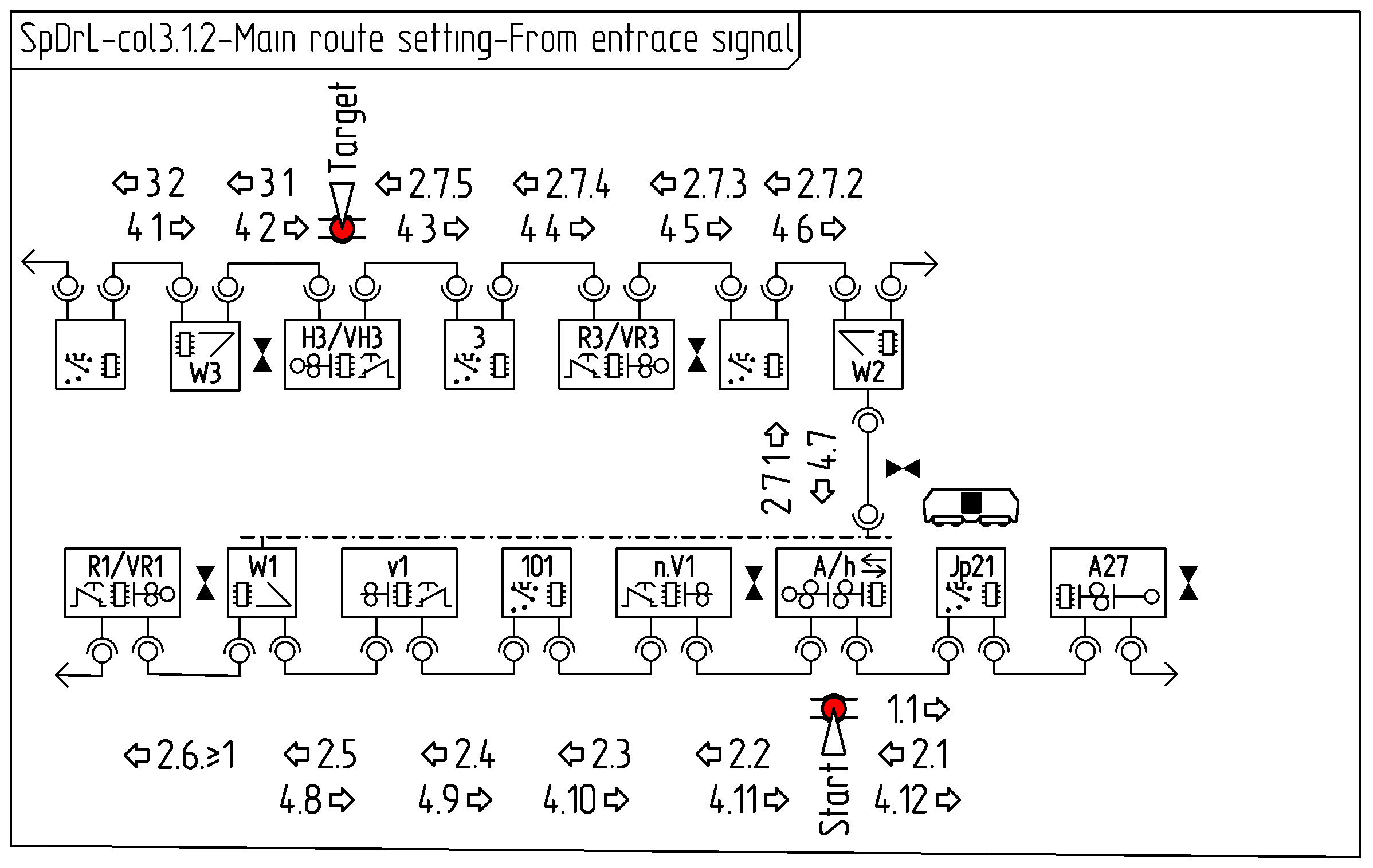
The second diagram covers a route between a exit signal and running track. The messages between the components and purpose of them are:
getMainRoute: Obtain CabNo
getMainRoute: Check if route is clear. Deliver CabNo to traction selectors. Set target point route at turnouts.
getMainRoute: Check if overlap route is clear.
setMainRoute: Set route status at main signals. Enable traction at traction selectors. Set and lock turnouts. Obtain lowest maximum speed of points. Set aspect at start main signal.
The diagrams below shows the communication between components to achieve this main route setting.
Message 1: getMainRoute
Component
Prerequisite
Action
Component
Prerequisite
Action
h
A
ZST pressed (Start). Not blocked. Not locked.
Send message 1.
Massage reference: 1.1 ⇨
Jp21
Destination message 1.
Message 2: getMainRoute
Component
Prerequisite
Action
Component
Prerequisite
Action
The last automatic block, here Jp21
Not vacant. Cab number is set.
Add Cab number to message 2. Send message 2.
Massage reference: 2.1 ⇦
h
A
ZST pressed (start). Not blocked. Not locked.
Pass message 2 through.
Massage reference: 2.2 ⇦
n.V1
Not locked.
Pass message 2 through.
Massage reference: 2.3 ⇦
101
Vacant. Not locked.
Pass message 2 through.
Massage reference: 2.4 ⇦
v1
Not locked.
Pass message 2 through.
Massage reference: 2.5 ⇦
W1
Vacant. Not blocked. Not locked.
Add maximum speed to message 2 for both directions. Send message 2 in both directions.
Massage reference: 2.6 ⇦ and 2.7.1 ⇧
W2
Vacant. Not blocked. Not locked.
Store direction message 2 came from. Add maximum speed to message 2. Send message 2.
Massage reference: 2.7.2 ⇦
103
Vacant. Not locked.
Pass message 2 through.
Massage reference: 2.7.3 ⇦
VR3
Not locked.
R3
ZZT pressed (Target) Not locked
Pass message 2 through.
Massage reference: 2.7.4 ⇦
3
Vacant. Not locked.
Pass message 2 through.
Massage reference: 2.7.5 ⇦
VH3
H3
Destination message 2.
Message 3: getMainRoute
Component
Prerequisite
Action
Component
Prerequisite
Action
H3
ZZT Pressed (Target). Not Blocked. Not locked
VH3
Not Blocked. Not locked
Send message 3.
Massage reference: 3.1 ⇦
W3
…
Massage reference: 3.2 ⇦
203
Destination message 3.
Message 4: setMainRoute
Component
Prerequisite
Action
Component
Prerequisite
Action
203
Not vacant. Cab number is set.
Enable traction from Cab number in massage 2. Send message 3.
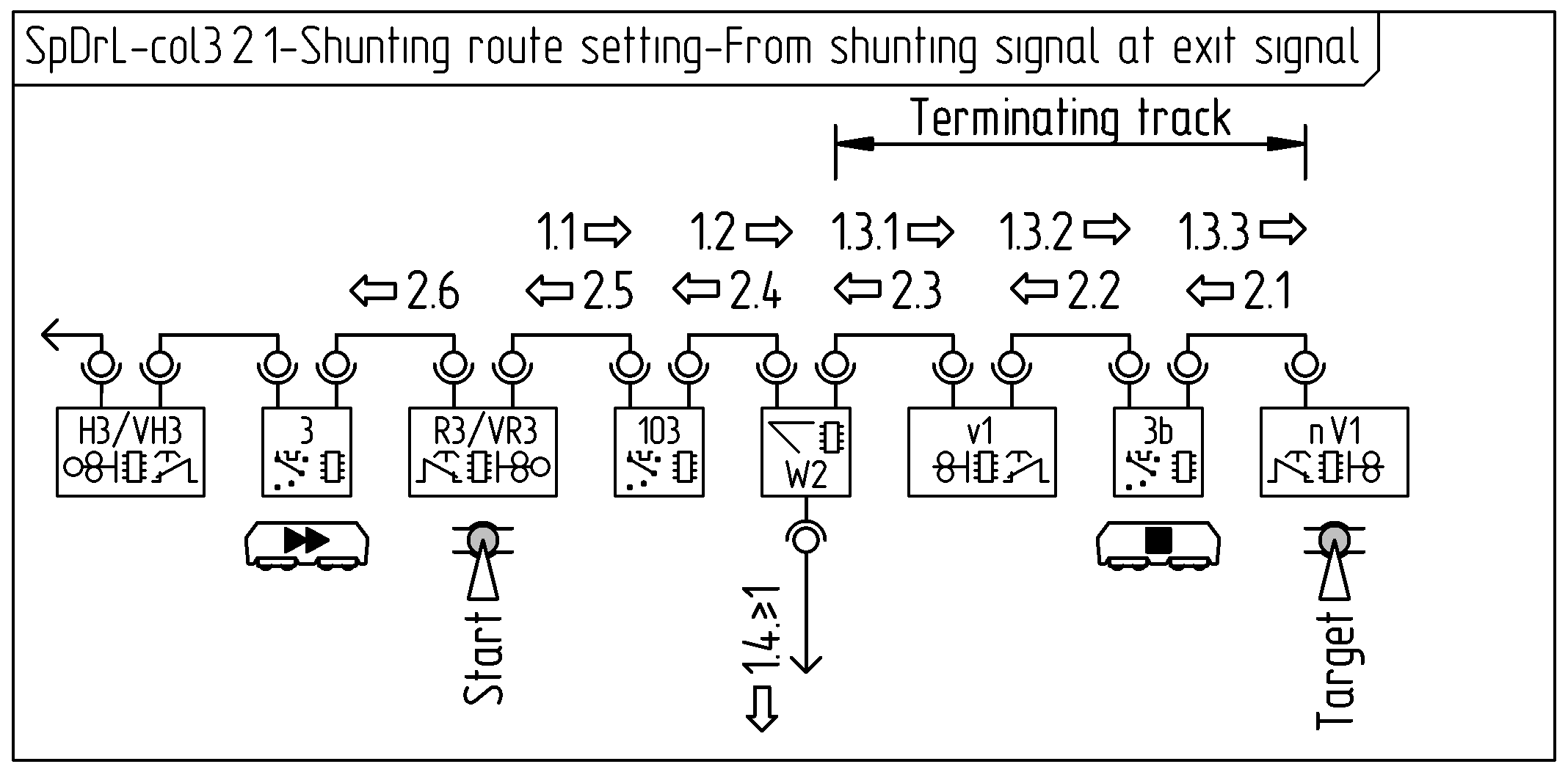
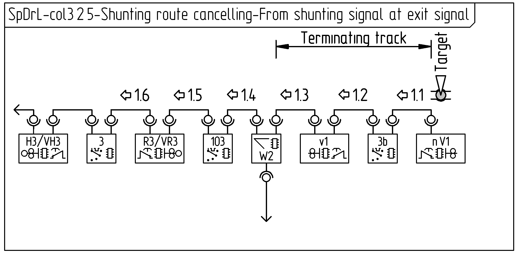
The collaboration diagrams, below shows the communication between components to achieve a shunting route settings.
The first diagrams covers a shunting route between a shunting signal at an exit signal to a terminating track. The messages and purpose of them between the components are:
getShuntingRoute: Check if no route is set. Set target point route at turnouts.
setShuntingRoute: Enable shunting traction at traction selectors. Lock turnouts. Show shunting allowed aspect.
Message 1: getShuntingRoute
Component
Prerequisite
Action
Component
Prerequisite
Action
VR3
VST pressed (Start). Not locked. Not blokked.
Send message 1.
R3
Not locked.
Pass message 1 through.
Massage reference: 1.1 ⇨
103
Pass message 1 through
Massage reference: 1.2 ⇨
W2
Vacant. Not Locked. Not blocked.
Pass message 1 to both turnout directions
Massage reference: 1.3.1 ⇨
v1
Not Locked. Not blocked.
Pass message 1 through
Massage reference: 1.3.2 ⇨
3b
Pass message 1 through
Massage reference: 1.3.3 ⇨
n.V1
Destination message 1.
Message 2: setShuntingRoute
Component
Prerequisite
Action
Component
Prerequisite
Action
n.V1
VZT pressed (Target). Not Locked. Not blocked.
Set lock Send message 2
Massage reference: ⇦ 2.1
3b
Allow traction Pass message 2 through
Massage reference: ⇦ 2.2
v1
Set lock Pass message 2 through
Massage reference: ⇦ 2.3
W2
Set lock Pass message 2 through to entry point of turnout
Massage reference: ⇦ 2.4
103
Allow traction Pass message 2 through
Massage reference: ⇦ 2.5
R3
Set lock Pass message 2 through
VR3
Set Lock Set shunting allowed signal aspect Pass message 2 through
Massage reference: ⇦ 2.6
3
Destination message 1. Allow traction.
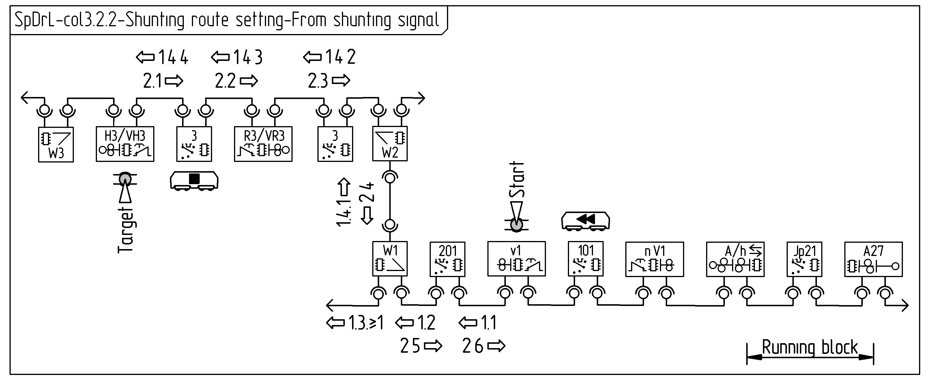
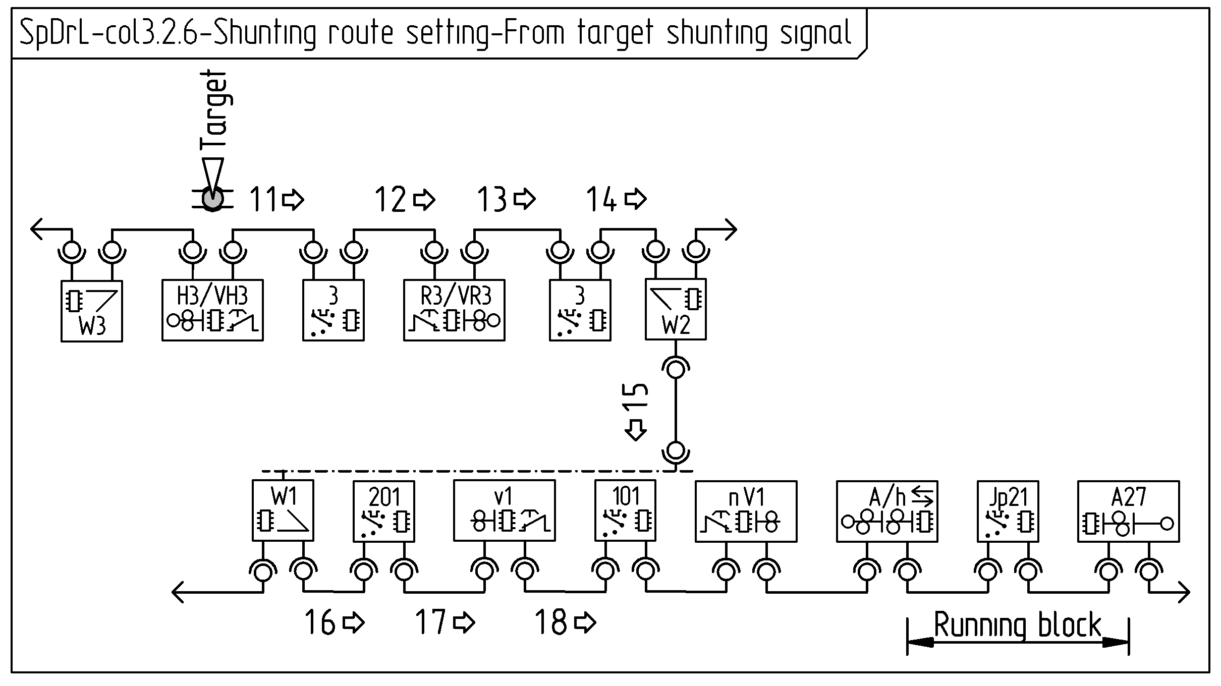
The second diagram covers a route from a shunting signal. The messages between the components and purpose of them are:
getShuntingRoute: Check if no route is set. Set target point route at turnouts.
setShuntingRoute: Enable shunting traction at traction selectors. Lock turnouts. Show shunting allowed aspect.
Message 1: getShuntingRoute
Component
Prerequisite
Action
Component
Prerequisite
Action
v1
VST pressed (Start)
…
Massage reference: 1.1 ⇦
201
…
Massage reference: 1.2 ⇦
W1
…
…
Massage reference: 1.3 ⇦ and 1.4.1 ⇧
W2
…
…
Massage reference: 1.4.2 ⇦
103
…
…
Massage reference: 1.4.3 ⇦
VR3
…
…
R3
…
…
Massage reference: 1.4.4 ⇦
3
…
…
Massage reference: 1.4.5 ⇦
Message 2: setShuntingRoute
Component
Prerequisite
Action
Component
Prerequisite
Action
H3
VZT pressed (Target)
…
VH3
…
Massage reference: 2.1 ⇨
3
…
…
Massage reference: 2.2 ⇨
R3
…
…
VR3
…
…
Massage reference: 2.3 ⇨
103
…
…
Massage reference: 2.4 ⇨
W2
…
…
Massage reference: 2.5 ⇩
W1
…
…
Massage reference: 2.6 ⇨
201
…
…
Massage reference: 2.7 ⇨
v1
…
…
Main route releasing interactionTrain detection
The collaboration diagrams, below shows the communication between components to achieve a main route releasing.
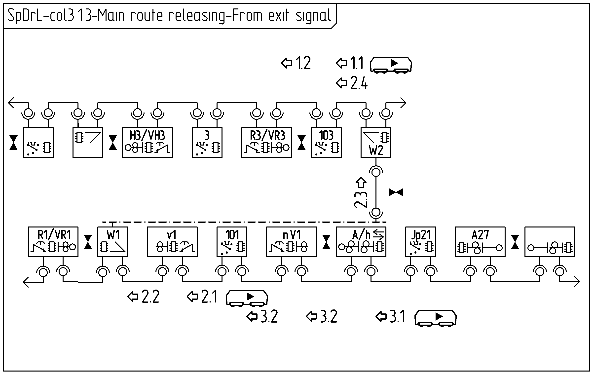
The first diagram covers main route releasing from an exit signal to a running track. The messages and purpose of them between the components are:
releasePartMainRoute: Sets passed signal at danger.
releasePartMainRoute: Unlocks part main route of vacant components.
releasePartMainRoute: Unlocks part main route of vacant components.
releasePartMainRoute: Unlocks part main route of vacant components.
Message 1: releasePartMainRoute
Component
Prerequisite
Action
Component
Prerequisite
Action
103
Changes to non vacant (Train enters section)
…
Massage reference: 1.1 ⇦
…
…
Message 2: releasePartMainRoute
Component
Prerequisite
Action
Component
Prerequisite
Action
103
Changes to vacant (Train leaves section)
…
Massage reference: 2.1 ⇦
…
…
Message 3: releasePartMainRoute
Component
Prerequisite
Action
Component
Prerequisite
Action
101
Changes to vacant (Train leaves section)
…
Massage reference: 3.1 ⇦
…
…
Message 4: releasePartMainRoute
Component
Prerequisite
Action
Component
Prerequisite
Action
Jp21
Changes to vacant (Train leaves section)
…
Massage reference: 4.1 ⇦
…
…
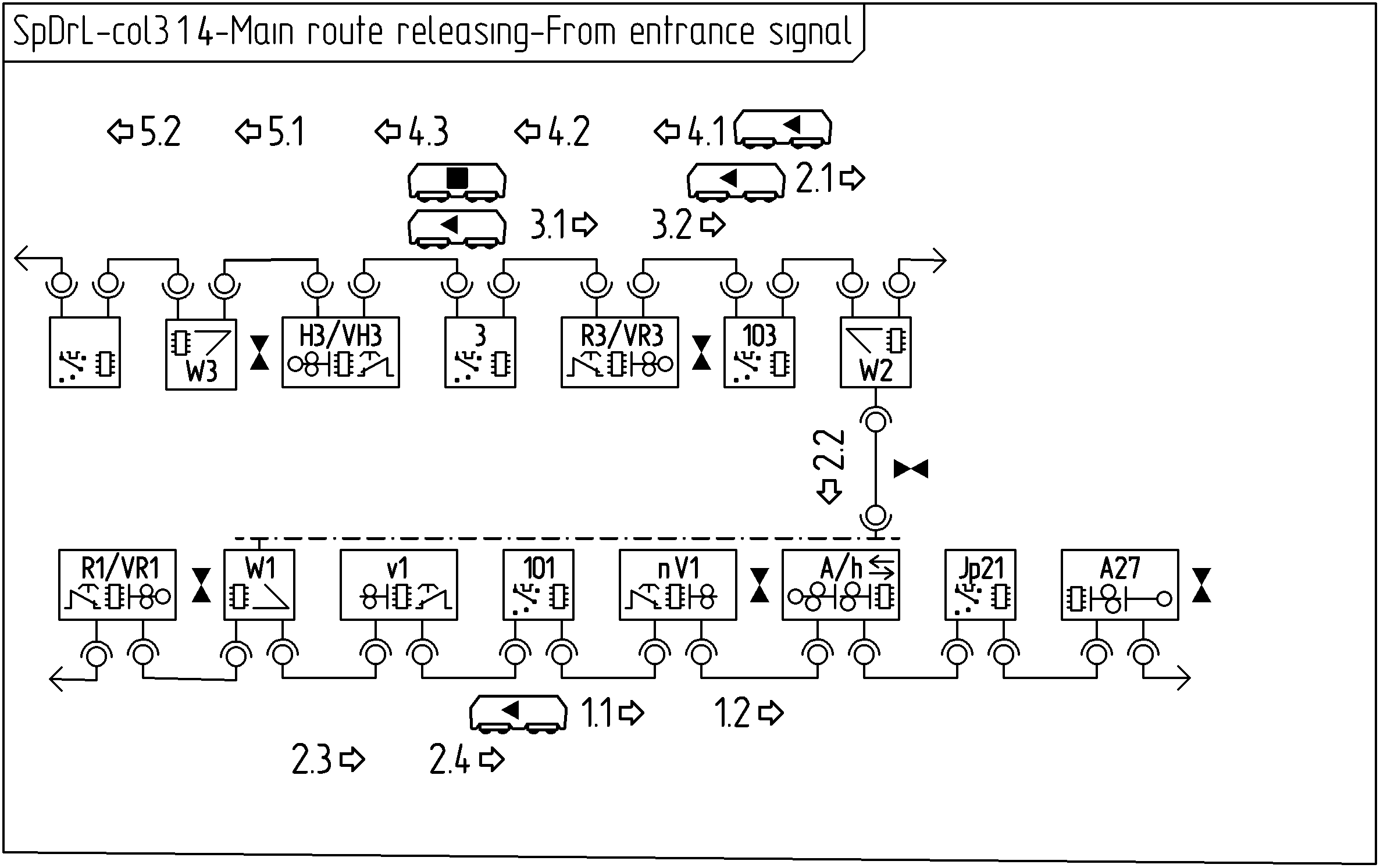
The second diagram covers main route releasing between a entrance and exit signal. The messages between the components and purpose of them are:
releasePartMainRoute: Sets passed signal at danger. Unlocks vacant components. Disengages traction.
releasePartMainRoute: Ditto.
releasePartMainRoute: Releases mainRouteSet next main or intermediate signal.
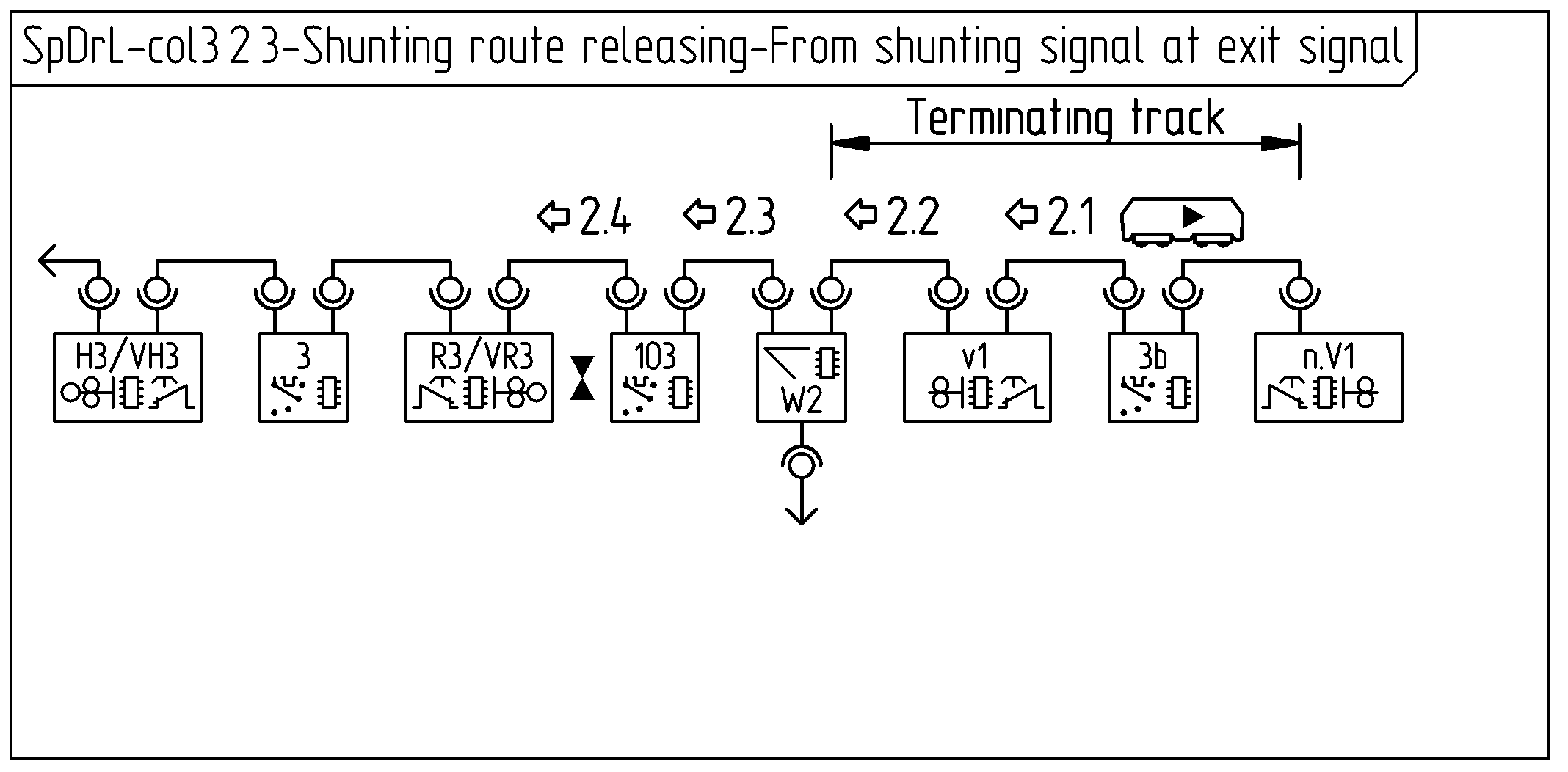
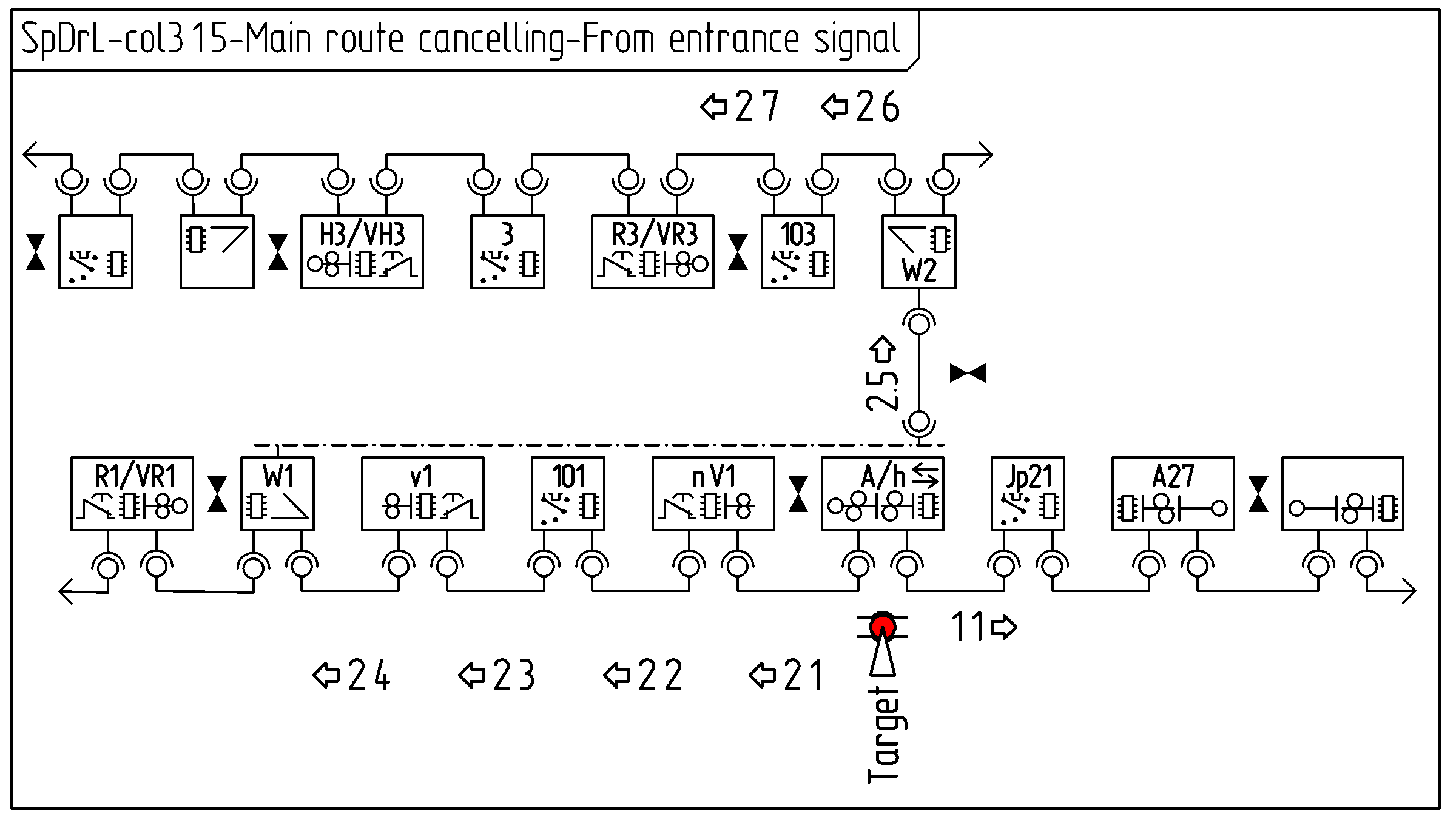
The collaboration diagrams, below shows the communication between components to achieve main route cancelling.
The first diagram covers main route cancelling between an exit and entrance signal. The messages and purpose of them between the components are: releasePartMainRoute: Disable traction of the traction selector at the adjacent block releasePartMainRoute: Clear route set status at main signals. Disable traction at traction selectors. Unlock turnouts.
Message 1:
Component
Prerequisite
Action
Component
Prerequisite
Action
…
…
…
Massage reference: …
…
…
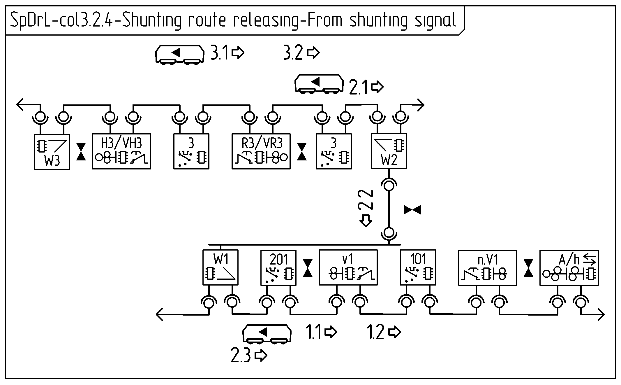
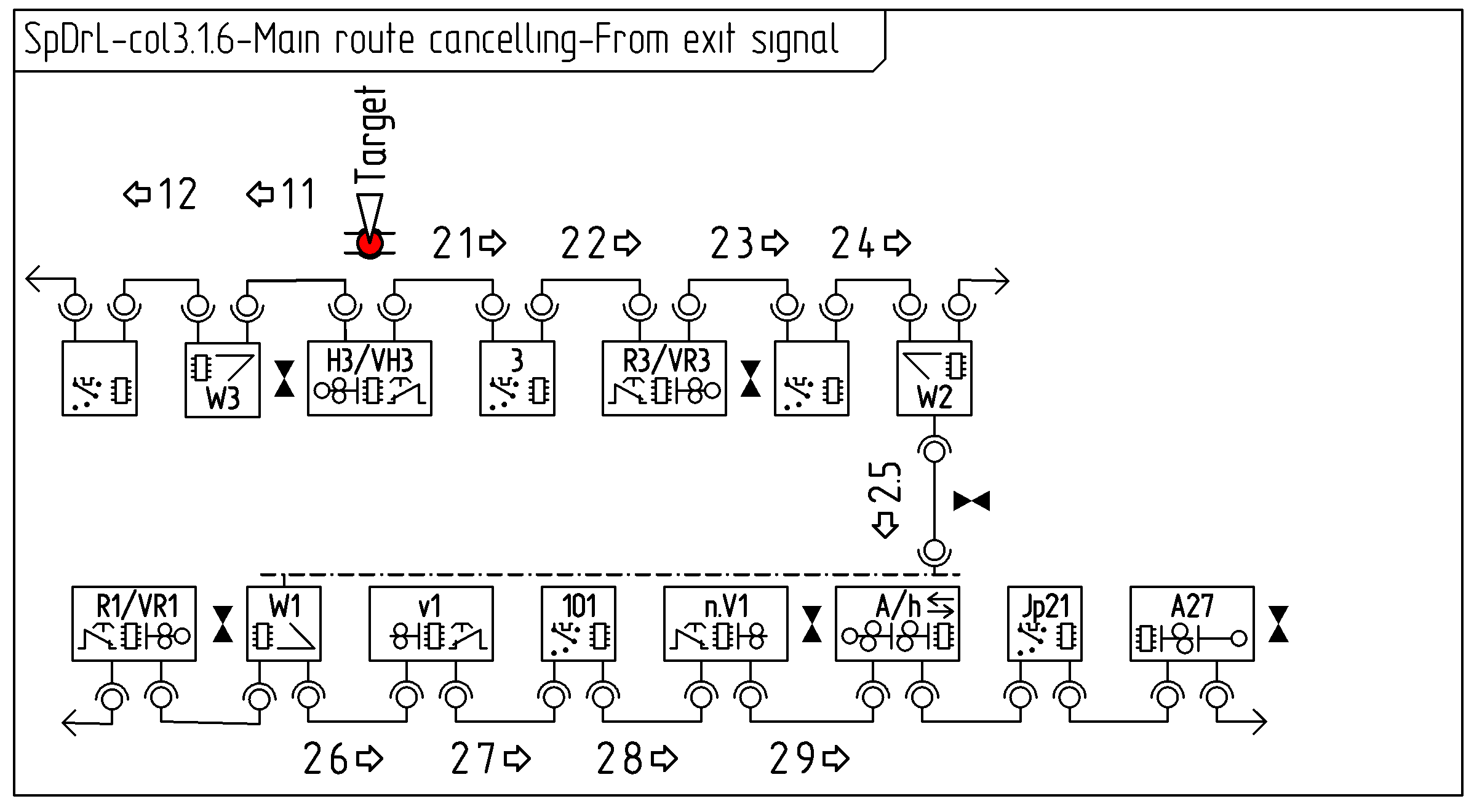
The second diagram covers a route between a entrance and exit signal. The messages between the components and purpose of them are: releasePartMainRoute: Disable traction of the traction selector of the overlap after the exit signal releasePartMainRoute: Clear route set status at main signals. Disable traction at traction selector