Page updated on 1 February 2026


Development and construction stages
The development and construction stages are completed as follows:
Before the next stage is started the previous stage are completed first for the whole model railway.
Stage 1
In stage 1 Turnout control and indication, and traction areas are employed:
- Only turnouts are controllable.
- This can be employed by pressing a common turnout button in the group tile area and a turnout button in the track plan of the SpDrL60 panel. The tiles of the switch point show the position of the points and if they are non vacant.
- The layout are divided in 8 traction areas.
- Traction areas can be connected to four cab controllers, selectable by rotary switches. This allows for a train controlled by a cab controller to run across several sections. Only one self propelled train is allowed in a traction area.
Place the two pin connector for a particular traction area at the front of the traction selector controller PCB.
The properties of the turnout and traction components are in compatible with all future functions in stage 2 up to 4.
Stage 2
In stage 2 individual control and indication of all infra elements are added:
-
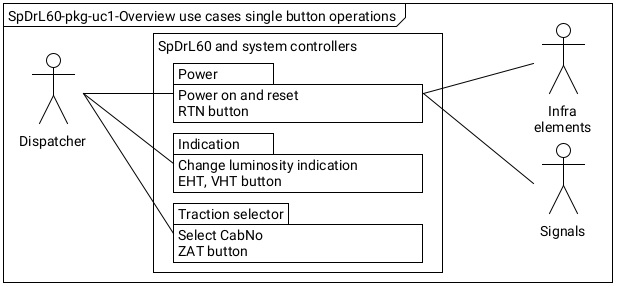
- Single button operation
- This entails pressing a button in the group tile area to reset the whole system, the selection of a cab to a traction section and setting the brightness of the LEDs of the SpDrL60 panel. See user case single button operations below.
-
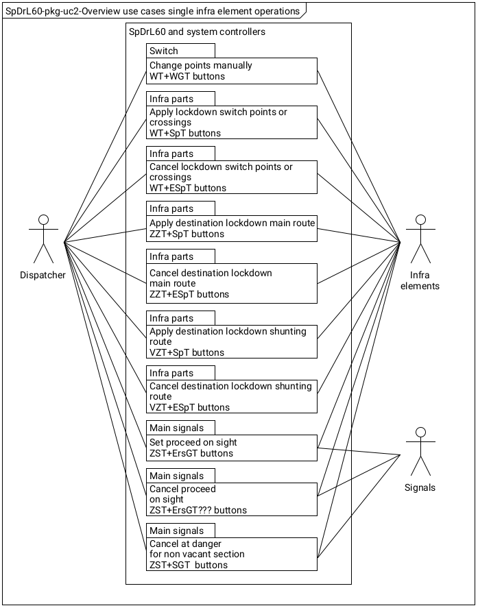
- Single infra element operations
- Single infra element operations shall entail pressing a button to operate a turnouts, a signals and an automatic blocks in combination by pressing an associated group button. See use case single infra element operations below.
The properties of the turnouts, traction components and single infra elements are compatible with all future functions in stage 3 and 4.
Traction areas in phase 2 are still selectable to cab-controllers by rotary switches.
Stage 3
In stage 3 control and indication of routes and cab assignment are added:
-
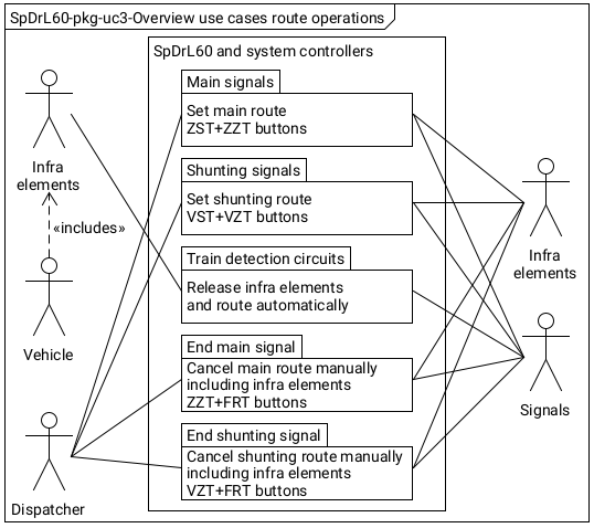
- Route operations
- Main or shunting route operations entails pressing a start button of a signal at the beginning of a requested route for a train and destination button of the signal or stub track where the train should terminate. The route is cancelled after the train has passed the route clearing point. See use case route operations below.
- Cab assignment
- A cab controller is automatically assigned to main route when the route is set. The cab controller is obtained from the traction component at the start of the route. The cab assigned to a route is changeable at a main traction section. Rotary switches to select cab controllers to traction areas will be employed for traction sections of shunting routes.
Stage 4
In stage 4 the control of line site signals are employed. They are controlled by command system components via a two wire multi master bus i.e.: I2C.