The structural model is to embody the geometric form of the system and the association between components. Not only of the SpDrL mosaic signalling panel, controller system and line site elements, but also of components, like the point motor turnout controller level.
The contents of the this web page is as follows:
Legend
Employed diagrams
To describe structural model of the command and control system the following Unified Modeling Language (UML) diagrams may be employed:
For the deployment model:
Deployment diagrams (dpm)
Component diagrams (cmp)
For the design model diagrams:
Package diagrams (pkg)
Composite structure diagrams
Object diagram (obj)
Sub routine diagrams
Controller components symbols
The symbols used for controller components are:
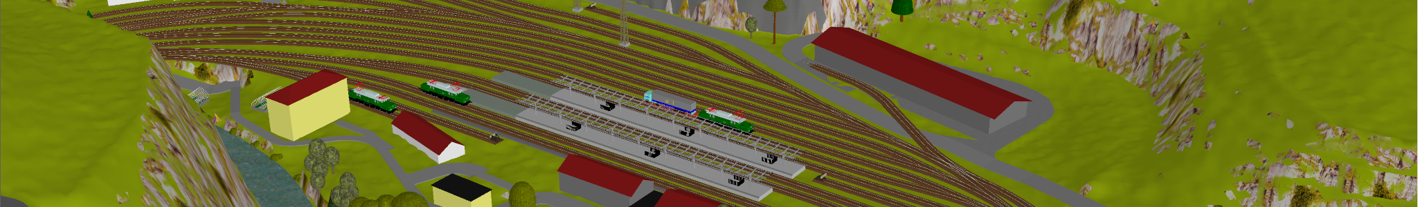
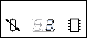
Turnout controller component with a µC
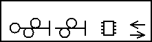
Track vacancy detector component
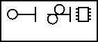
Traction selector controller component with a µC
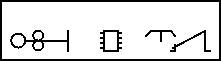
Block signal controller component with a µC
Entrance and distance signal controller component with direction running track and a µC
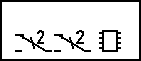
Exit and shunting signal controller component with (de)coupler and a µC
Shunting signal controller component with (de)coupler and a µC
Rail loop controller component with a µC
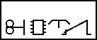
Cab unit
Nomenclature abbreviations
Abbreviations methodology used in interfaces diagrams and for the labels on PCBs is:
NAME INTERFACE[interface number][function|[(function,function)]], e.g.: Cn, T2(n,r)
Duplex data transmission interface functions are denoted by t and r, e.g.: R1(t,r)
Simplex functions are denoted by a and a,b., e.g. L(a,b).
Function abbreviations shall be unique related to one interface abbreviation, but may be repeated at others.
Interface abbreviations
List with interface abbreviations used in interfaces diagrams and for the labels on PCBs:
A
Aspect interface
C
Condition interface
D
Display interface
G
General interface
I
Infrastructure rail interface
K
Key pressed interface
L
Line site signals interface
M
Marker
N
Non vacancy detected interface
P
Pulse machine interface.
R
Route interface
S
Switch status interface.
T
Track status interface
U
Voltage interface
V
Vehicle cab unit interface
W
Way pointer interface
Deployment model
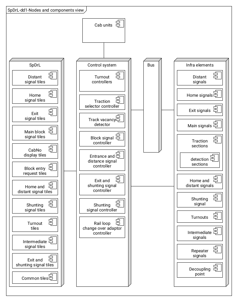
Overview nodes and components
The overall structural system is shown in the deployment diagram (dd) below.
Node deployment
SpDrLNode
Mosaic control panel consist of tiles. Tiles may have one button for control operation or one or more LEDs for indication.
The tiles control and indicate the status of the associated controller. They shall only be powered from the front of the PCBs of these controllers which shall be located in sub racks.
Cab unitNode
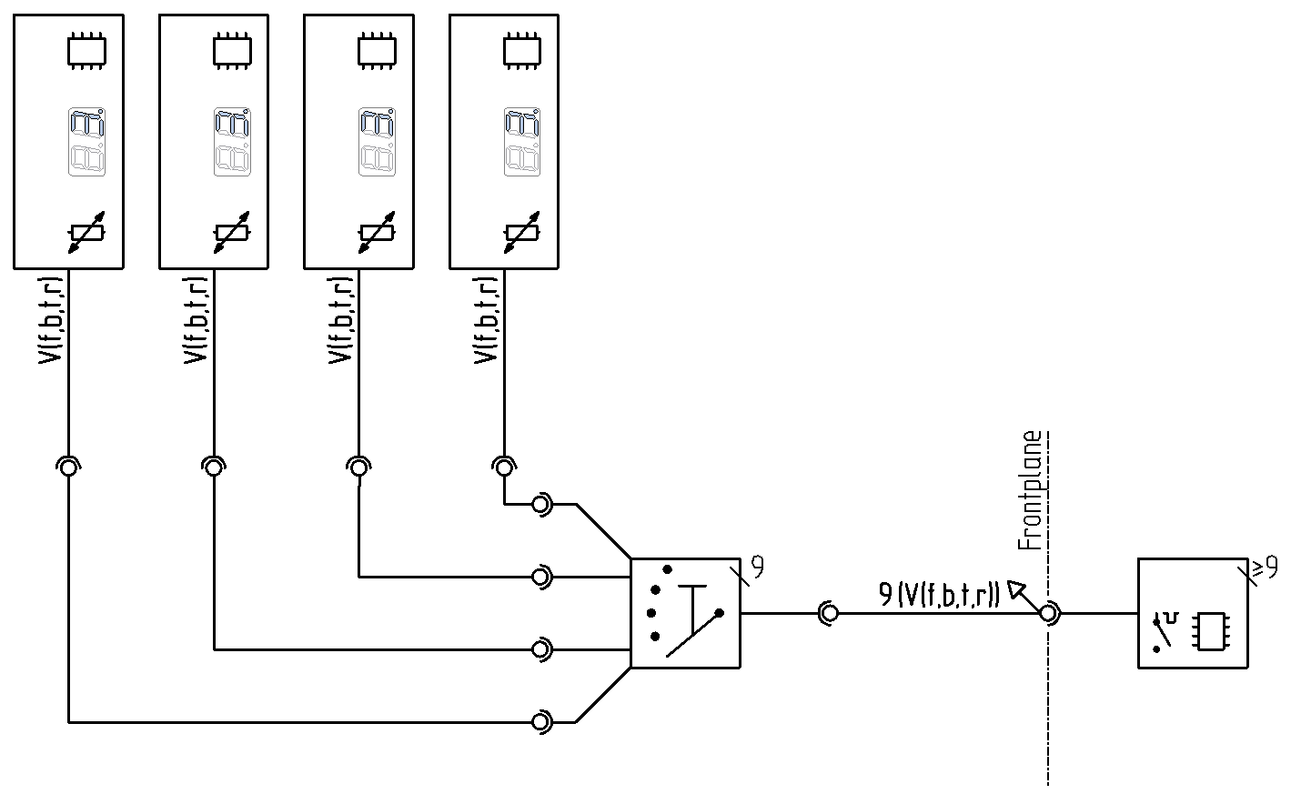
The cab units represent the drivers cabine. Each controls the speed and direction of a particular train and the allowed speed. There shall be provision for four cab units to be connected.
At stage 1 and 2 one and up to nine traction selector controllers are switched to a traction unit by a traction area switch. There shall be a total of nine traction areas.
Interfaces of cab units with traction selector controllers stage 1 and 2:
V(f,b,t,r)
Vehicle cab unit interface.
Signal interface to control the speed of a self propelled vehicle and a duplex point to point interface about showing the aspect of approaching signal and acknowledgement on the cab unit.
Provided and required interfaces, PWM designated f for forward and b for backward dierction and UART duplex point to point data wires t for transmit and r for receive..
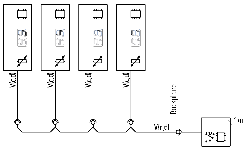
At stage 3 and 4 one of more traction selector controllers may be switched to a traction unit using software addressing.
Interfaces of cab units with traction selector controllers stage 3 and 4:
V(t,r)
Vehicle cab unit movement control and signal aspect interface,
Synchronous, multi-master and multi-slave, single-ended, serial communication bus interface for vehicle movement and showing the aspect of approaching signal and acknowledgement on the cab unit.
Provided and required interfaces. I2C designated c for clock and d for data.
These interfaces shall be available at all positions of PCBs on the backplane of the sub racks except for those with non vacancy detector.
Control systemNode
The control system consists of components for individual tasks controlled by a µC, except for train detection.
These components are connected to SpDrL tiles, train detection section, traction sections and turnouts with discrete wiring. These interfaces will be available at the front of their PCB.
Each of these component are connected together according to the track to exchange messages as stated in chapter 'Usage model'. This will be in a serial fashion.
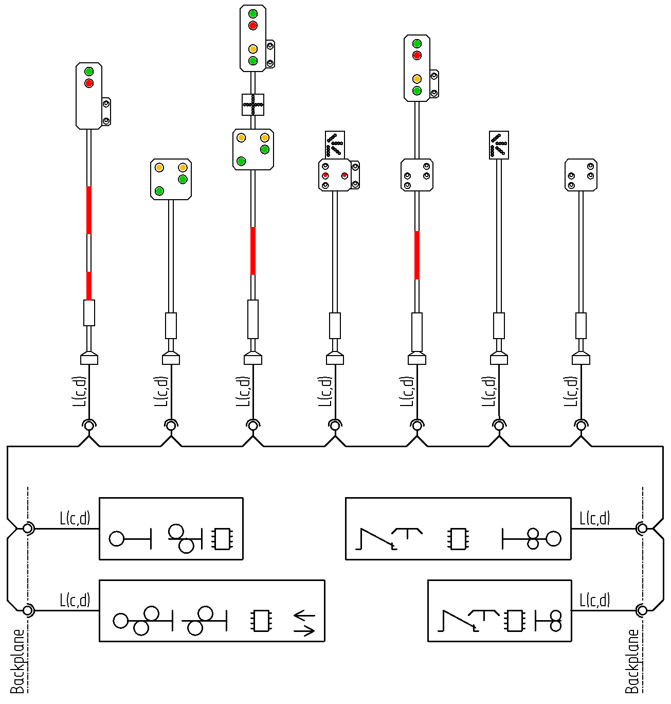
BusNode
The bus is only for indication. In particular the aspects of signal along the track. For this purpose a I2C or similar shall be employed.
Interfaces of signalling controllers with line site signals:
L(c,d)
Line site signal aspect interface
Synchronous, multi-master and multi-slave, single-ended, serial communication bus interface with address and aspect of approaching signal.
Provided interface by signalling controllers. I2C designated c for clock and d for data..
This interface shall be available at all positions of PCBs on the backplane of the sub racks.
Infra elementsNode
The infra elements are:
Track sections, turnouts and decouplers interfaced by discrete circuits
Line site signals interfaced by a bus.
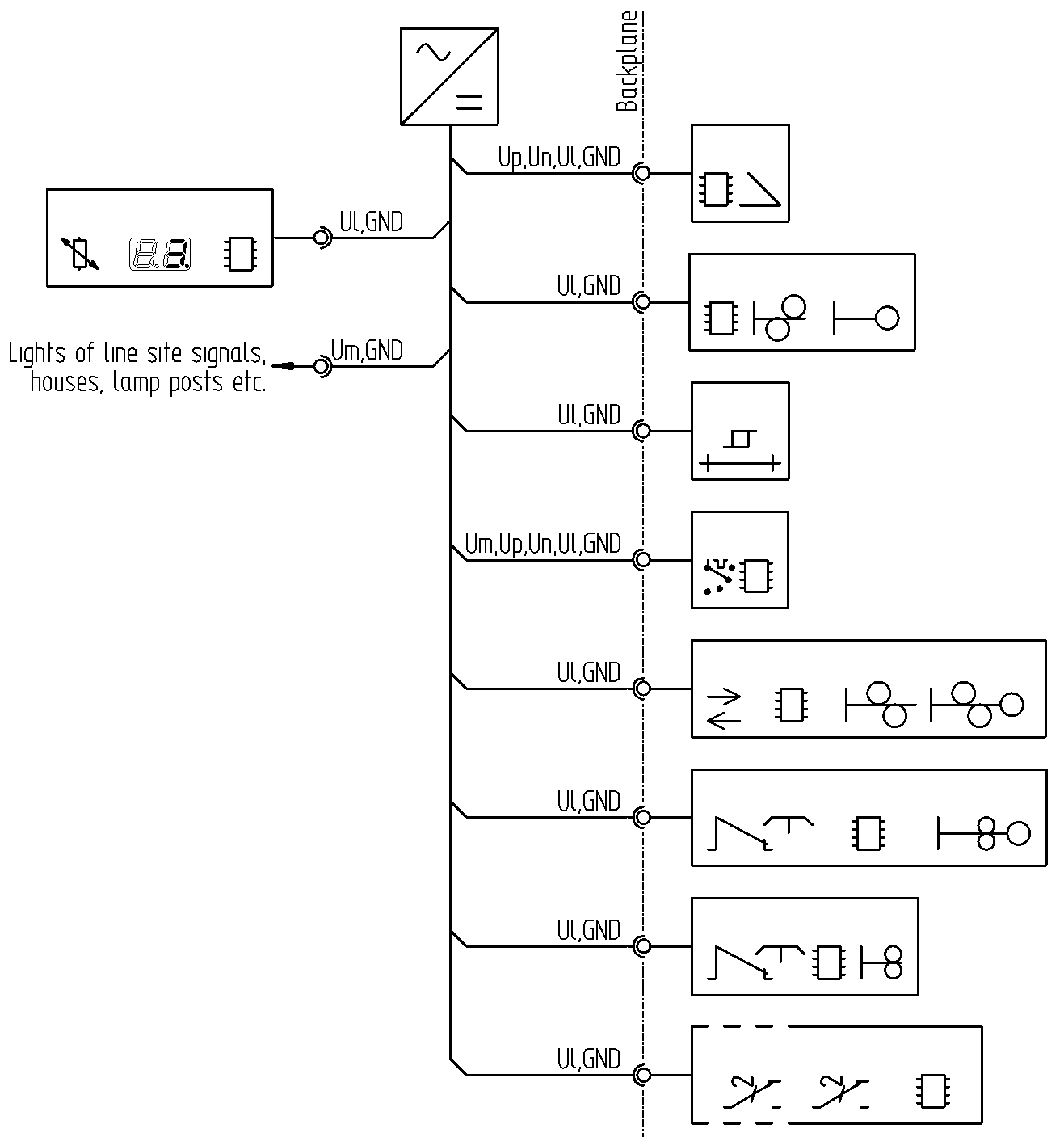
Power deployment
Below the deployment of power is shown. These will be available at all positions for PCBs on the backplane.
Deployment of supplying power:
Ul
logic voltage (+5V)
Up
positive high voltage (+12V)
Un
negative high voltage (−12V)
Um
miscellaneous voltage (+5V)
GND
Ground (0V)
These supplies shall be available at all positions of PCBs on the backplane of the sub racks.
Component deployment
This chapter is about the deployment model of composite components.
CommonDeployment
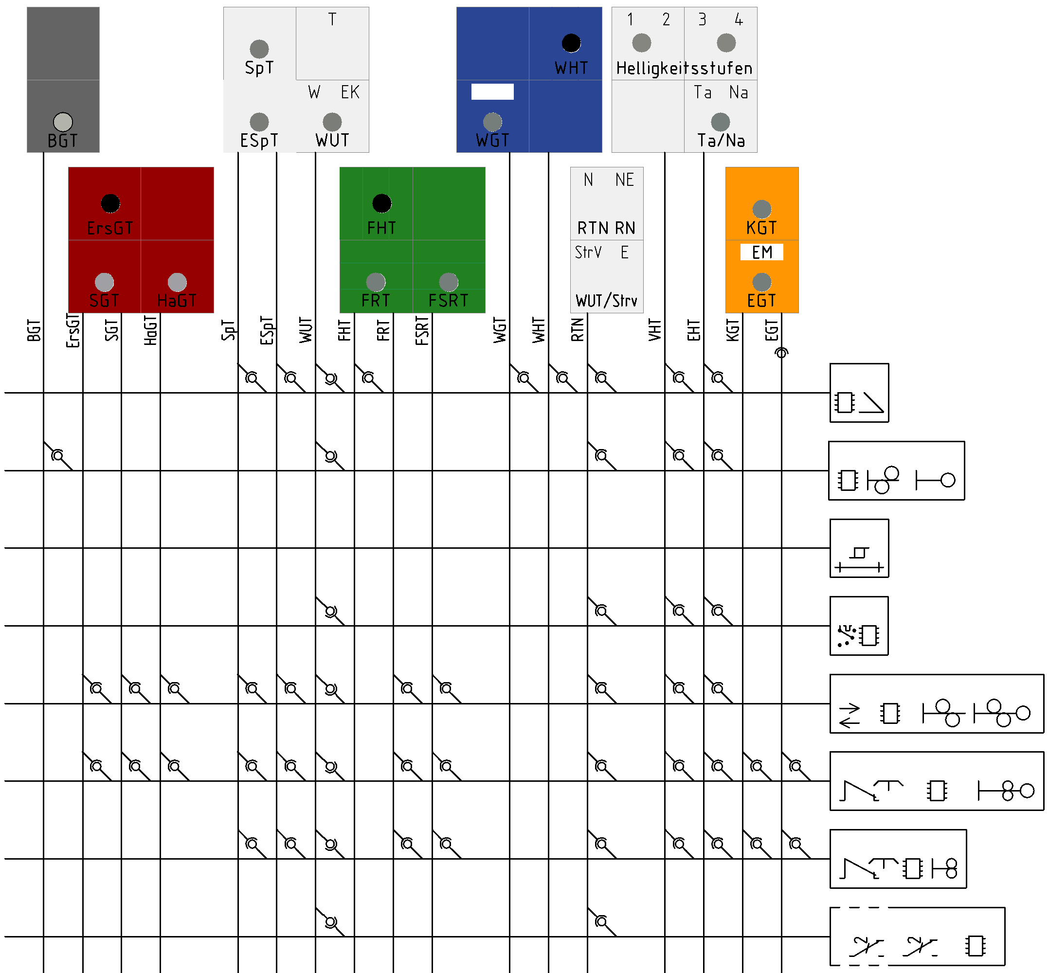
The physical deployment of common controls to all controller components for single button, single infra element and route operations is shown below.
Required interface by common tiles SpDrl60 of 1 discrete logic wire:
WUT
Weckerunterbrechertaste. Bus is used to sound alarm.
Provided interfaces by common tiles SpDrl60 of discrete logic wires:
BGT
Blockgruppentaste? pressed
ErsGT
Ersatzsignalgruppentaste pressed.
SGT
Signalgruppentaste pressed.
HaGT
Haltgruppentaste pressed.
SpT
Sperrtaste pressed.
ESpT
Entsperrtaste pressed.
FHT
Fahrstraßenhilfsauflösetaste? pressed.
FRT
Fahrstraßenrücknahmetaste pressed.
FSRT
Schutzwegrücknahmetaste pressed.
WGT
Weichengruppentaste pressed.
WHT
Weichenhilfstaste? pressed.
RTN
Ortsnetzrücksteltaste (Grundstellung) pressed.
EHT
Erhöhenhelligkeittaste pressed.
VHT
Verringernhelligkeittaste pressed.
KGT
Kuppelunggruppetaste pressed.
EGT
Entkuppelunggruppetaste pressed.
These interfaces shall be available at all positions of PCBs on the backplane of the sub racks.
A 16 to 4 coder shall be used for the provided interfaces to reduce the wires from the common tiles via the backplanes and also most of the input ports of the µC on the controllers boards.
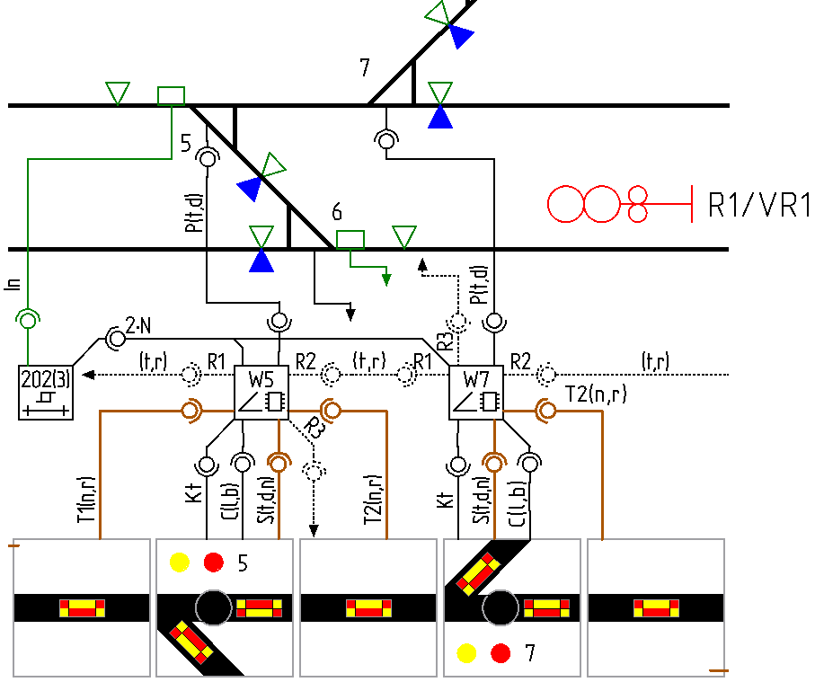
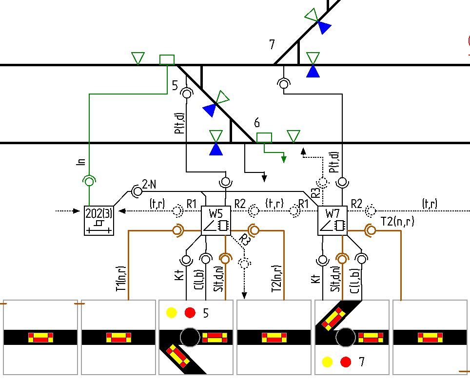
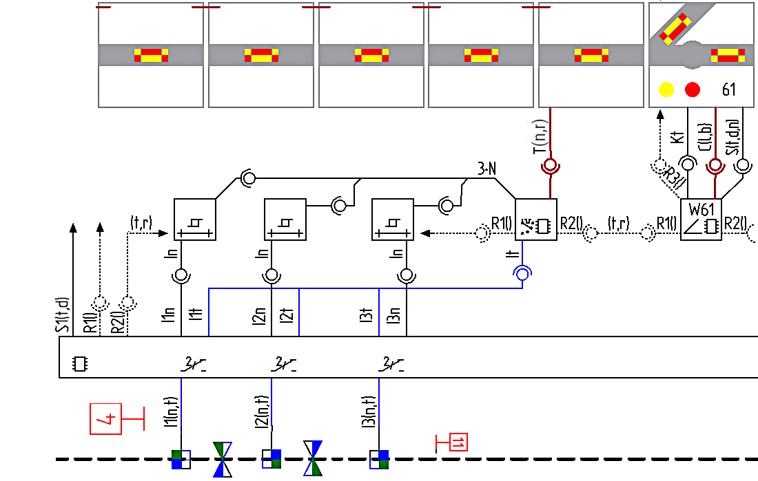
TurnoutsDeployment
The physical deployment of turnouts in the SpDrl60, control system en infra element nodes is shown in the figure below.
Discrete Interfaces of turnout controllers with the tiles of SpDrl60 and lineside components:
Rn(t,r)
Route setting interface: n = 1 is route setting interface towards point n = 2 is route setting interface at through route n = 3 is route interface at diverging route.
Three provided or required interfaces. UART half duplex wires designated Rnt for transmit and Rnr for receive.
P(t,d)
Pulse machine interface.
Lets the turnout to change direction and to gets its position.
Provided or required interface. 2 Wires designated Pt for through and Pd for diverging route.
N
Non vacancy detected interface.
Non vacancy indication for point and traction selector controllers.
Required interface. 1 Wire designated N.
Tn(n,r)
Track status interface:
Track status interface with a number pertains to adjacent tiles to a turnout tile: n = 1 is tile next towards point n = 2 is tile at through route n = 3 is tile at diverging route.
Track status indication tiles i.e. red for non vacant and white for route is set.
Provided interface. 2 Wires designated Tnn for non vacant and Tnr for route is set. The sequence of the numbering is in the signal numbering direction.
Kt
Key pressed interface turnout.
Gets a key press to toggle points of a turnout.
Required interface. 1 Wire designated Kt for turnout.
S(t,d,n)
Switch status interface.
Showing the position of the points with the status of the turnout i.e. red for non-vacant and white for not non-vacant and red or white flashing if the turn out is malfunctioning.
Provided interface, 3 Wires designated St for the through route set, Sd for the diverting route set and Sn if the turnout is not non-vacant.
C(l,b)
Condition interface.
Condition status turnout, i.e.: white light on for route locked and red light for in blocked.
Provided interface, 2 wires designated Cl for locked and Cb for in blocked
All these interfaces are at the front of the PCB with turnout controllers
Track vacancy detectorsDeployment
The physical deployment of track vacancy detectors in the SpDrl60, control system en infra element nodes is shown in the figure below.
Discrete Interfaces with the tiles of SpDrl60 and lineside components:
In
Infrastructure rail interface.
Rail circuit non vacancy detector.
Required interface, 1 wire designated In for non vacant.
n·N
Non vacancy detected interface.
Non vacancy indication for point and traction selector controllers.
Three provided interfaces (but only one may be required), one wire each designated n·N for sequence number and Non vacancy detected.
The indication of the non vacant status on the track tiles is handled by the traction selection amplifier. Hence there is no interface with the track tiles.
All these interfaces are at the front of the PCB with track vacancy detectors.
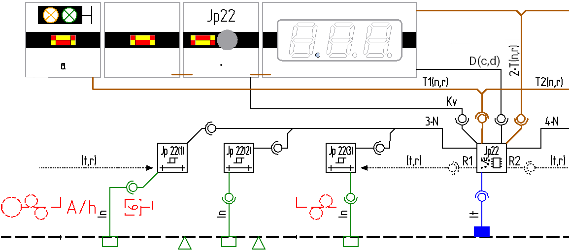
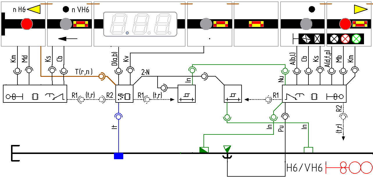
Traction selector amplifiersDeployment
The physical deployment of traction selector amplifiers in the SpDrl60, control system en infra element nodes is shown in the figure below.
Discrete Interfaces with tiles and lineside components:
Rn(t,r)
Route setting interface:
n = 1 in the signal numbering direction
n = 2 in the opposite signal numbering direction.
Two provided or required interfaces. UART half duplex wires designated Rnt for transmit and Rnr for receive.
Kv
Key pressed interface.
Gets a button key press to select the next cab unit
Required interfaces. 1 Wire designated Kv for vehicle cab unit.
D(c,d)
Display interface.
Alphanumeric display screen to show the ID of the connected vehicle cab unit and type of movement or automatic train control.Screen interface.
Provided interface. Simplified I²C (without address) interface wires designated c for clock and d for data.
It
Infrastructure rail interface.
Rail circuit vehicle traction.
Provided interface. 1 Wire designated It for traction.
n·N
Non vacancy detected interface.
Non vacancy indication from track vacancy detector.
8 required interfaces (a lesser amount may be provided). 1 Wire each designated n·N for sequence number and Non vacancy detected
T(n,r)
Track status interface.
Track status principal track section.
Track status indication tiles i.e. red for non vacant and white for route is set.
Provided interface. 2 Wires designated Tnn for on vacant and Tr for route is set.
Tn(n,r)
Track status interface.
Track status interface with a number pertains to additional tiles with track status interface, e.g. at distance signals, distance speed signs.
Track status indication tiles i.e. red for non vacant and white for route is set.
Provided interface. 2 Wires designated Tnn for non vacant and Tnr for route is set. The sequence of the numbering is in the signal numbering direction.
All these interfaces are at the front of the PCB with traction selection amplifier controllers
Block signalsDeployment
The physical deployment of block signals in the SpDrl60, control system en infra element nodes is shown in the figure below. The block signals are not shown on the SpDrl60 due to their automatic block operation.
Discrete Interfaces with other controller components:
Rn(t,r)
Route setting interface:
n = 1 in the signal numbering direction
n = 2 in the opposite signal numbering direction.
Two provided or required interfaces. UART half duplex wires designated Rnt for transmit and Rnr for receive.
All these interfaces are at the front of the PCB with Block signal controllers.
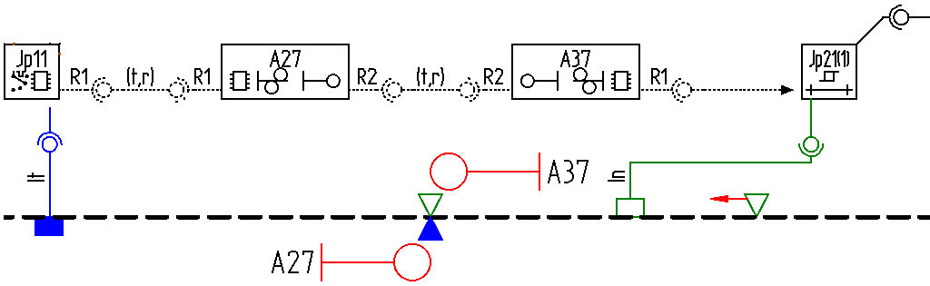
Entrance with distance signalsDeployment
The physical deployment of entrance with distance signals in the SpDrl60, control system en infra element nodes is shown in the figure below.
Discrete Interfaces with other controller components:
Rn(t,r)
Route setting interface:
n = 1 in the signal numbering direction
n = 2 in the opposite signal numbering direction.
Two provided or required interfaces. UART half duplex wires designated Rnt for transmit and Rnr for receive.
Mb
Marker route set interface
Sets the begin marker of a route that is set.
Provided interface. 1 Wire designated Mb for the begin marker.
A(d,f,p)
Aspect interface.
Lets the entrance signal indicate three aspects, i.e.: red for danger, green for free and white for proceed on sight (PoSA).
Provided interface. 3 Wires designated d for danger, f for free and p for proceed on sight.
Kb
Key pressed interface.
Gets a pressed a key press to set the begin of a main route.
Required interface. 1 Wire designated Kb for begin.
Md
Marker route set interface.
Sets the destination marker of a route that is set.
Provided interface. 1 Wire designated Md for the destination marker.
Cb
Condition interface.
Lets the red blocked notification light indicate the entrance signal is manually in blocked.
Provided interface. 1 Wire designated b for in blocked
A(c,m)
Aspect interface.
Lets the distance signal at the entrance signal indicate two aspects, i.e. yellow for caution and green for main signal free.
Provided interface. 2 Wires designated c for caution and m for main signal free.
Kd
Key pressed interface.
Gets a key press to set the destination of a main route.
Required interface. 1 Wire designated Kd for destination.
A1(c,m)
2 aspects for the 1st additional signal
Lets the distance signal for the entrance signal indicate two aspects, i.e. yellow for caution and green for clearmain signal free.
Provided interface. 2 Wires designated c for caution and m for main signal free.
W(n,x)
Way pointer interface.
Let the way pointers indicate the set train direction of automatic blocks on a running track, i.e.: the entrance towards the entrance signal and the exit away from the entrance signal.
Provided interface. 2 Wires designated n for entrance and x for exit.
Kw
Key pressed interface.
Changes allowed way of a vehicle on a running track with automatic block.
Required interface. 1 Wire designated Kw for way running track.
All these interfaces are at the front of the PCB with entrance and distance signal controllers.
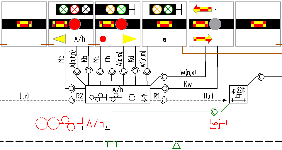
Exit with shunting signalsDeployment
The physical deployment of exit with shunting signals in the SpDrl60, control system en infra element nodes is shown in the figure below.
Discrete Interfaces with other controller components:
Rn(t,r)
Route setting interface:
n = 1 in the signal numbering direction
n = 2 in the opposite signal numbering direction.
Two provided or required interfaces. UART half duplex wires designated Rnt for transmit and Rnr for receive.
Km
Key pressed interface.
Gets a pressed button a key press to set a main route.
Required interface. 1 Wire designated Km for main route.
Mb
Marker route set interface
Sets the begin marker of a route that is set.
Provided interface. 1 Wire designated Mb for the begin marker.
Ks
Key pressed interface.
Gets a pressed button for a shunting route.
Required interface. 1 Wire designated Ks for shunting.
Cb
Condition interface.
Lets the red blocked notification light indicate the exit signal or destination is manually in blocked.
Provided interface. 1 Wire designated b for in blocked
A(b,l)
Aspect interface.
Lets the shunting signal at the exit signal indicate two aspects, i.e. white horizontal for shunting banned and white diagonal for shunting ban lifted
Provided interface. 2 Wires designated b for banned and l for lifted.
A(d,f,p)
Aspect interface.
Lets the entrance signal indicate three aspects, i.e.: red for danger, green for free and white for proceed on sight (PoSA).
Provided interface. 3 Wires designated d for danger, f for free and p for proceed on sight.
Md
Marker route set interface.
Gets a key press to set the destination of a main route.
Required interface. 1 Wire designated Kd for destination.
Km
Key pressed interface.
Gets a pressed button for a main route.
Required interface. 1 Wire designated Km for main route.
Nu
Non vacancy detected interface.
Detection of non vacancy of a train detection section, which is interrupted by the exit and shunting controller if a decoupling is in progress.
Required and provided interface, 1 wire designated u for uncoupling.
T(n,r)
Track status interface.
Track status principal track section.
Track status indication tiles i.e. red for non vacant and white for route is set.
Provided interface. 2 Wires designated Tnn for on vacant and Tr for route is set.
Pu
Pulse machine interface
Execute the decoupling of two vehicles.
Provided interface. 1 Wires designated Pu for uncoupling.
All these interfaces are at the front of the PCB with exit and shunting signal controllers.
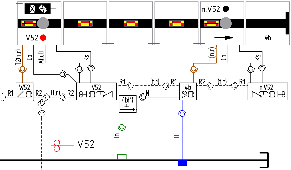
Shunting signalsDeployment
The physical deployment of shunting signals in the SpDrl60, control system en infra element nodes is shown in the figure below.
Discrete Interfaces with other controller components:
Rn(t,r)
Route setting interface:
n = 1 in the signal numbering direction
n = 2 in the opposite signal numbering direction.
Two provided or required interfaces. UART half duplex wires designated Rnt for transmit and Rnr for receive.
Ks
Key pressed interface.
Gets a pressed button for a shunting route.
Required interface. 1 Wire designated Ks for shunting.
Cb
Condition interface.
Lets the red blocked notification light indicate the exit signal or destination is manually in blocked
Provided interface. 1 Wire designated b for in blocked
A(b,l)
Aspect interface.
Lets the shunting signal at the exit signal indicate two aspects, i.e. white horizontal for shunting banned and white diagonal for shunting ban lifted
Provided interface. 2 Wires designated b for banned and l for lifted.
All these interfaces are at the front of the PCB with shunting signal controllers.
Rail loop change over adaptorDeployment
The physical deployment of rail loop change over adaptor in the SpDrl60, control system en infra element nodes is shown in the figure below.
Discrete Interfaces with other controller components:
Rn(t,r)
Route setting interface:
n = 1 in the signal numbering direction
n = 2 in the opposite signal numbering direction.
Two provided or required interfaces. UART half duplex wires designated Rnt for transmit and Rnr for receive.
In(n,t)
Infrastructure rail interface.
Rail connection for non vacancy detector and vehicle traction .
Provided respectively required interface. 2 Wires designated Inn for non vacant and tn for vehicle traction. The n denotes the sequence number in the signal numbering direction.
In
>Infrastructure rail interface.
Rail circuit non vacancy detector.
Required interface, 1 wire designated In for non vacant.
Inn
Infrastructure rail interface.
Loop connection non vacancy detector.
Required interface. 1 Wire designation Inn for the n th non vacancy detection.
It
Infrastructure rail interface.
Rail circuit vehicle traction.
Provided interface. 1 Wire designated It for traction.
Int
Infrastructure rail interface.
Loop connection vehicle traction.
Provided interface. 1 Wire designation Int for the n th vehicle traction.
S1(t,d)
Switch status interface points.
Gets the location position turnout points at entrance of rail loop i.e.: a for pointsStraight and b for pointsDeverted. This will determine the polarity, traction and detection of the detection and traction connections to the track in the rail loop.
Required interface. 2 Wires designated St for the through route set and Sd for the diverting route set.
All these interfaces are at the front of the PCB with rail loop change over adaptor controllers.
Design model
This chapter covers the design of the individual components grouped by above composite components.
Turnouts
Turnout tile
Schematic of the turnout tile, which is directly connected to the turnout controller.
Reference front header connections:
To the turnout controller.
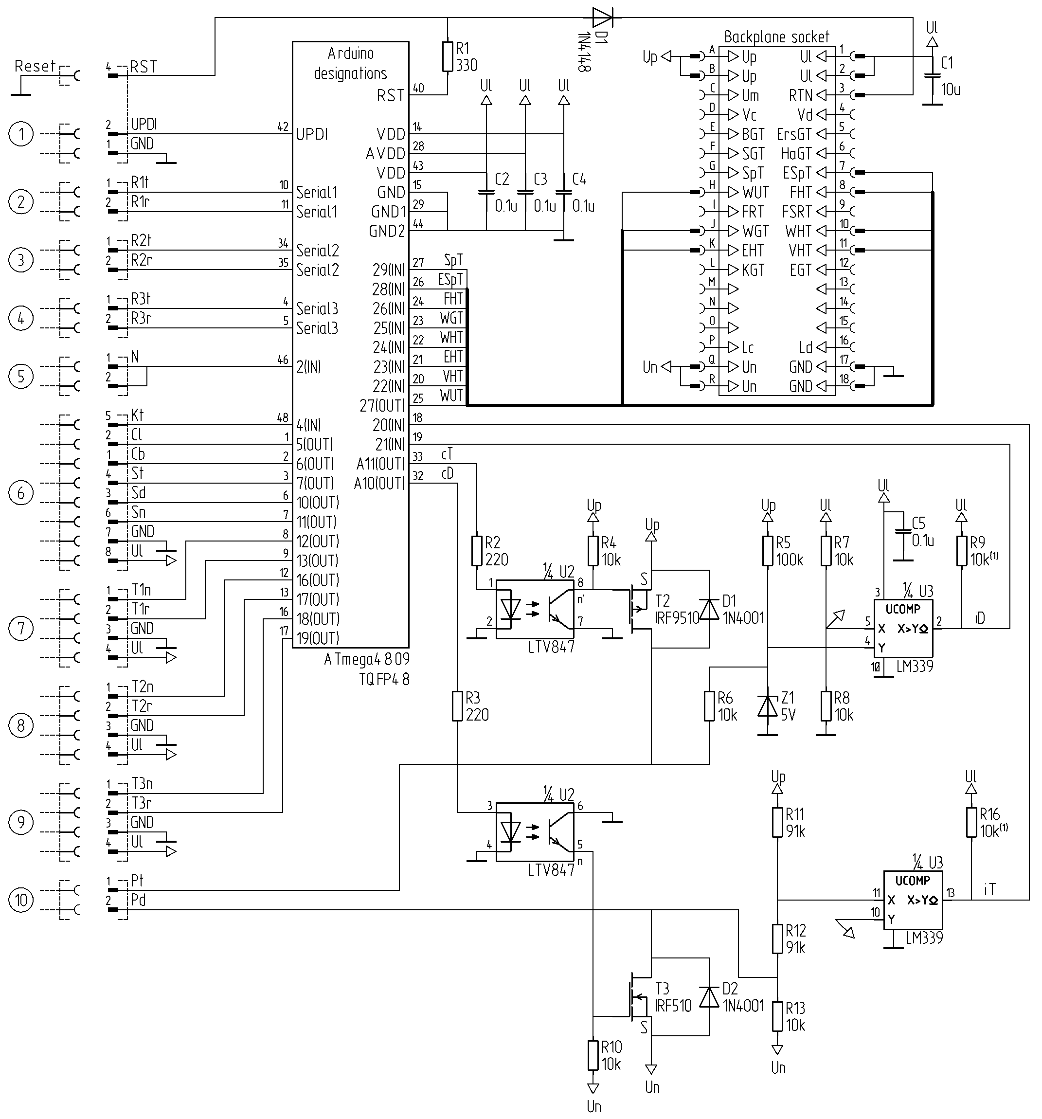
Turnout controller
The 34 I/O pins require an ATmega4809.
Reference front header connections:
To the UPDI programmer for uploading code
To adjacent component entry track
To adjacent component through track
To adjacent component at diverging track
To one or two traction selector amplifiers.
To one or two traction selector amplifiers.
To the adjacent track indicator tile to the entry track
To the adjacent track indicator tile to the through track
To the adjacent track indicator tile to the diverging track
To turnout infra element
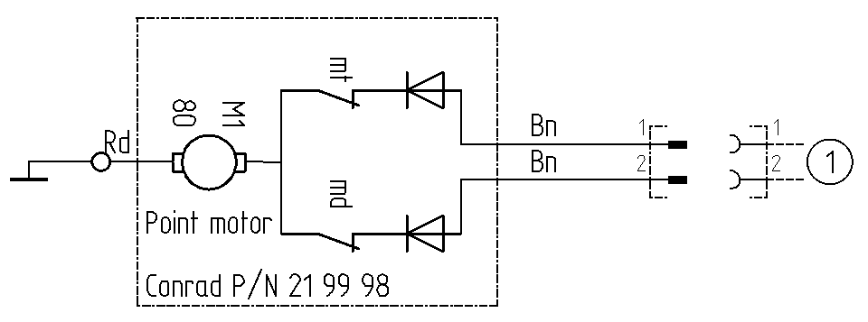
Turnout infra element
For a turnout infra element a point motor from Conrad P/N 21 99 98 or Tillig 86112 shall be used depending on the available space. Use the Tillig 86112 in difficult to reach places as this point motor is more reliable. For Tillig EW1, turnouts without a polarised point frog, use point motor 83532 for a left turnout and Tillig 83531 for a right turnout.
Reference front header connections:
To a turnout controller.
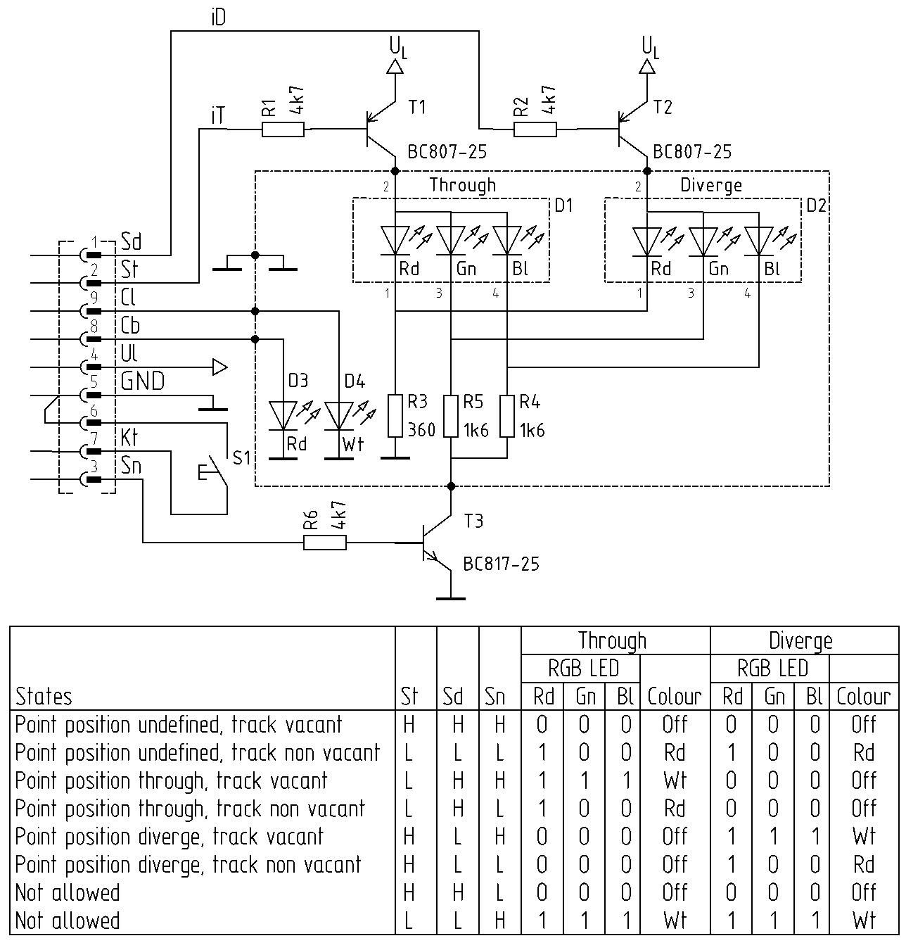
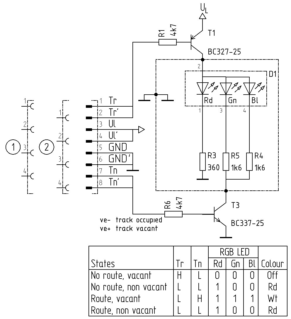
Track indicator
Track indicator tile
Structural model, design model, track status tile.
Reference front header connections:
To a traction selector amplifier or turnout controller
To the next track indicator tile.
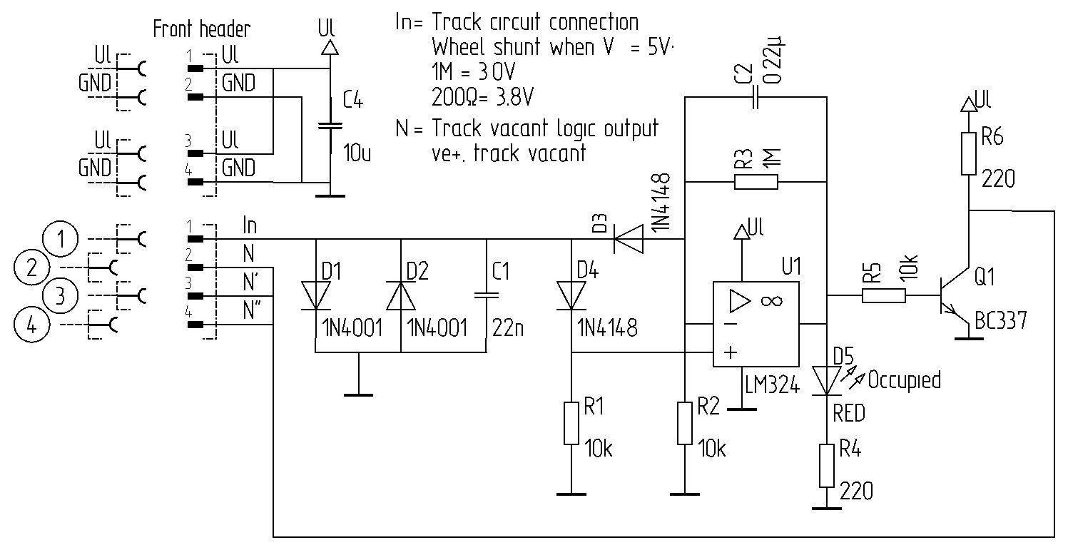
Train detector
Structural model, design model, train detector
Reference front header connections:
To a non vacancy detection section
To a turnout or traction selector amplifier controller
To an other turnout or traction selector amplifier controller if any
To an other turnout or traction selector amplifier controller if any
Track vacancy track section
Track vacancy track section...
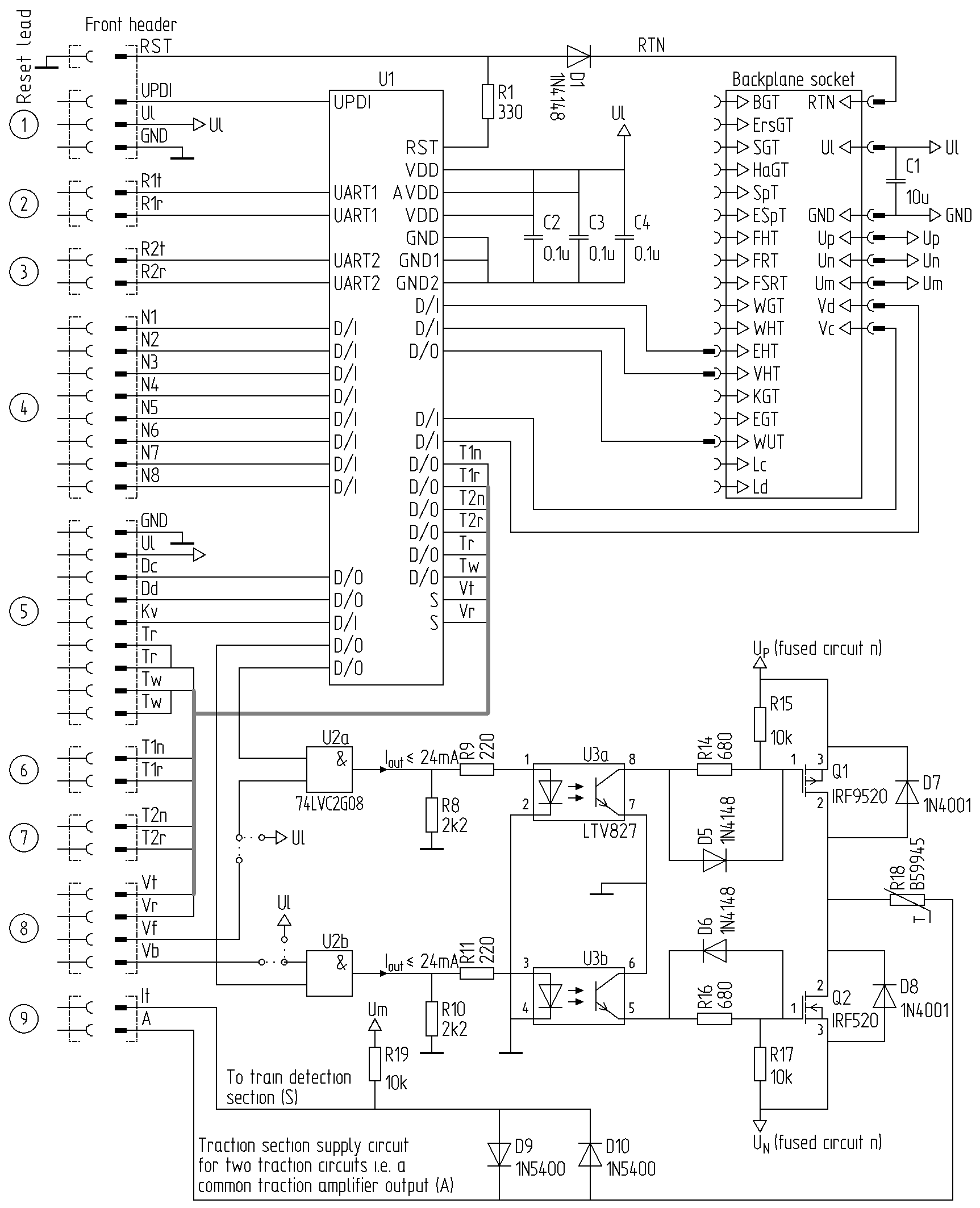
Traction selector amplifier
Traction selector amplifier tile
Traction selector amplifier tile...
Parts:
TM1650|TM1652: 8-segment × 4 digits led driver
Libraries for ATmega:
TM1650|TM1652: github.com/maxint-rd/TM16xx
Also includes code to display strings (rudimentary characters)
To one or more non vacancy detectors or destination tile.
To train cab unit number display tile and adjacent train cab unit number select key tile
To one of the adjacent tiles for route and non vacancy indication
To the other adjacent tiles for route and non vacancy indication
To cab unit (stage 1 and 2)
To the non vacancy detection section (Pen A is probably redundant)
Link between: 1 and 2: At stage 1 and 2 when up to nine traction selector controllers are switched to a traction selector amplifier controller by a traction area switch. 1 and 3: At stage 3 and 4 when one of more traction selector controllers may be switched to a traction unit using software addressing.
Traction selector amplifier track section
Traction selector amplifier track section...
Block signals
Block signal tile
Block signals...
Block signal controller
Block signal controller...
Common Interfaces and power supply backplane:
GND
Common ground
Power supply connection at back of PCB. 1 Connection.
UL
Logic power +5 V
Power supply connection at back of PCB. 1 Connection.
X(a,b)
Drop interface to bus to control the aspect a particular line site signal:
Provided interface, 2 Wires designated a and b
Line side block signal
Line side block signal...
Entrance with distance signals
Entrance with distance signal tiles
Entrance with distance signal tiles...
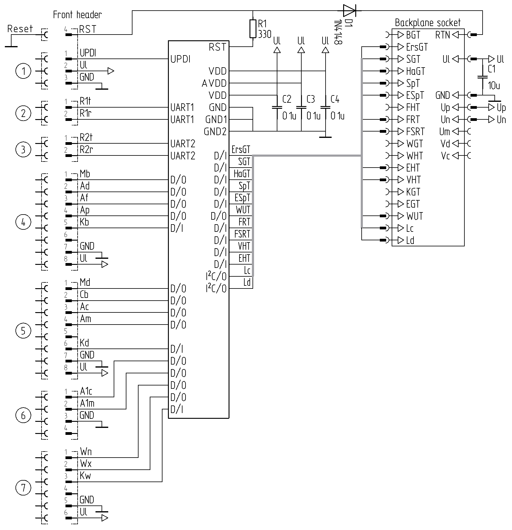
Entrance with distance signal controller
Structural model, design model, entrance signal controller...
Reference front header connections:
To the UPDI programmer for uploading code
To oner of adjacent component controllers in any
To the other adjacent component controller if any
To main entry signal tile.
To distant signal tile below main entry signal
To distance signal tile placed before entry signal
To automatic block tile running track.
Line side entrance with distance signal
Line side entrance with distance signal...
Exit with shunting signals
Exit with shunting signal tiles
Exit with shunting signal tiles...
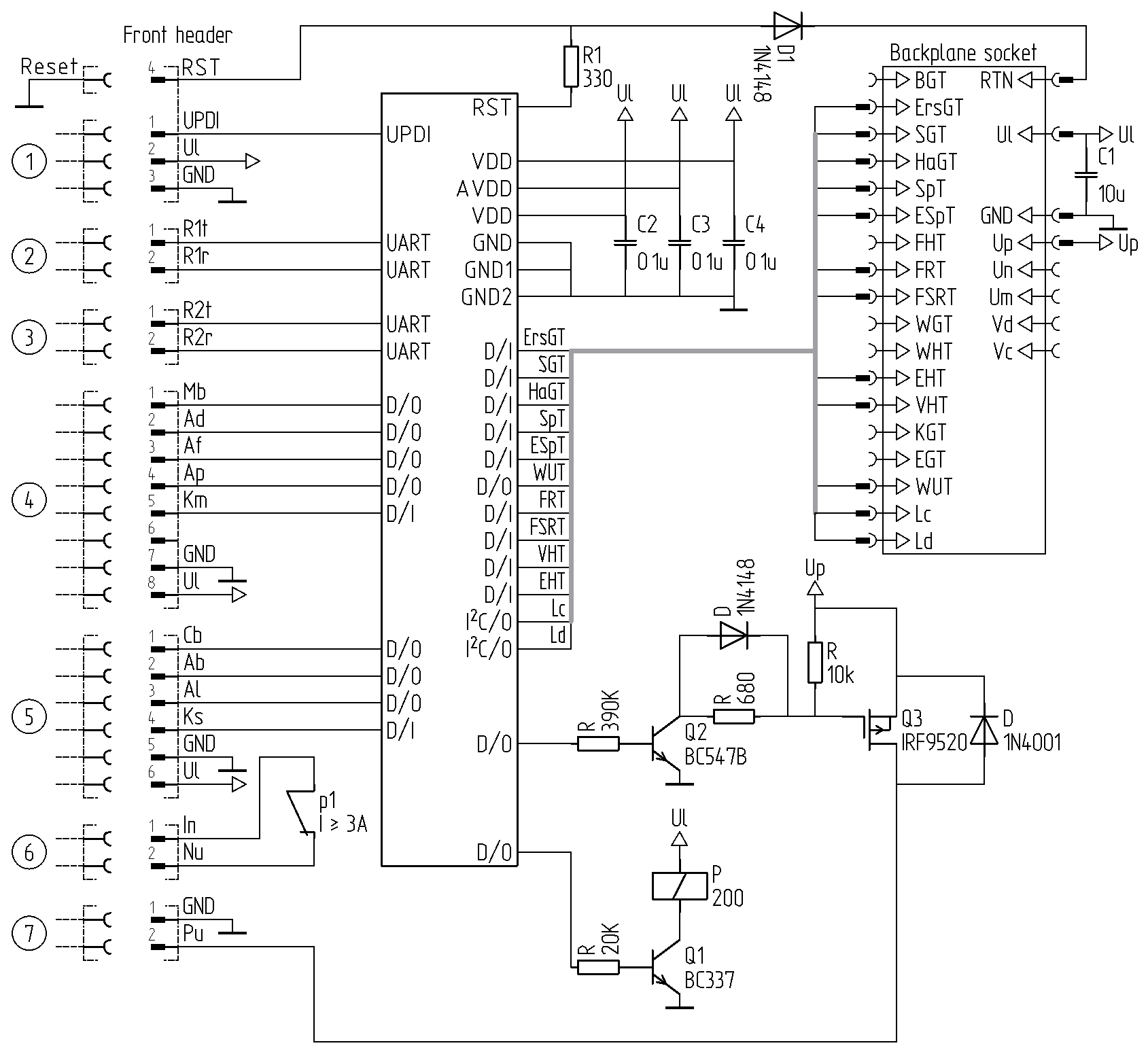
Exit with shunting signal controller
Structural model, design model, exit signal with uncouple controller...
Reference front header connections:
To the UPDI programmer for uploading code
To adjacent component controller
To adjacent component controller
To main exit signal or destination tile
To shunting signal tile below main exit signal
Insulating traction current section with uncoupled loc
To the uncoupling solenoid.
Line side exit with shunting signal
Line side exit with shunting signal...
Shunting signals
Shunting signal tile
Shunting signal tile...
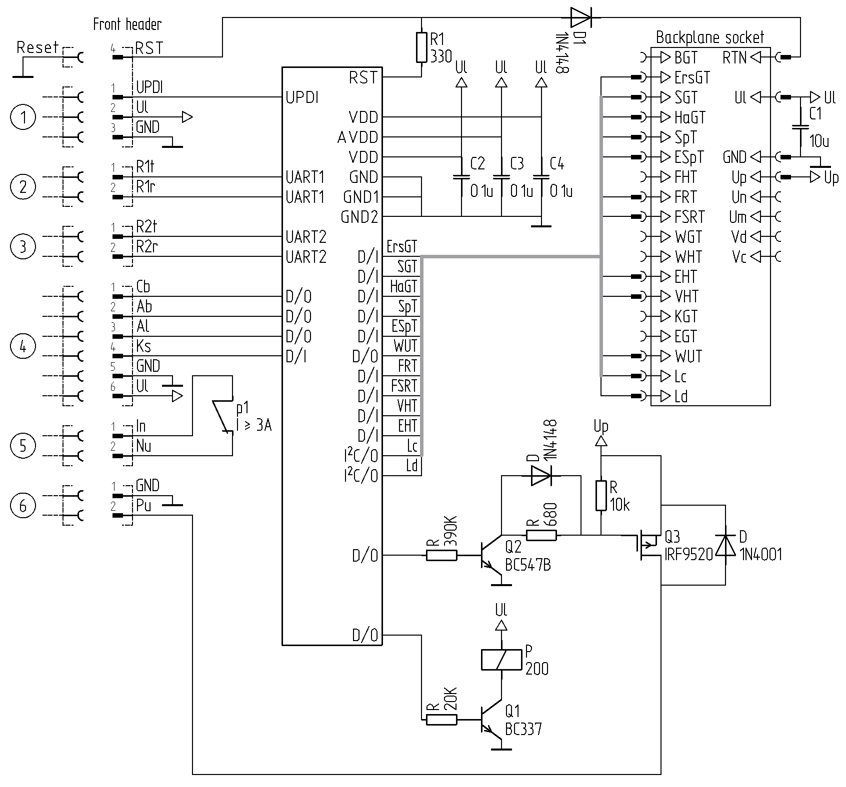
Shunting signal controller
Structural model, design model, shunting signal with uncouple controller...
Reference front header connections:
To the UPDI programmer for uploading code
To adjacent component controller
To adjacent component controller
To shunting signal tile.
Insulating traction current section with uncoupled loc.