

ÖBB BR 1020
The original Tillig ÖBB BR 1020 art.No: 01562 was equipped with marginal running properties and only front headlights. It decided to replace them. The steps were:
- Unclip and remove the front and rear end housings from the bogies
- Remove the screw near the pantograph and unclip the main housing
- Unclip and remove the weights
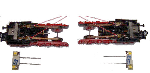
- Unsolder and disconnect the cables from the bogies
- Remove locking pins from bogies, remove bogies and their cardan shafts
- Unsolder the suppression choke and other parts from the sheet metal conductor
- Remove both sheet metal conductors including the current springs for the bogies (electrical connection to the bogies is later established via the wires of the motor)
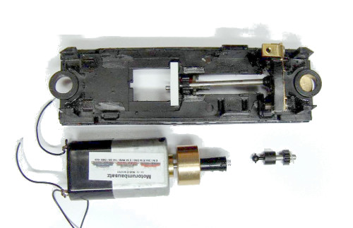
- Remove the motor pin and remove the motor and its pinion shaft
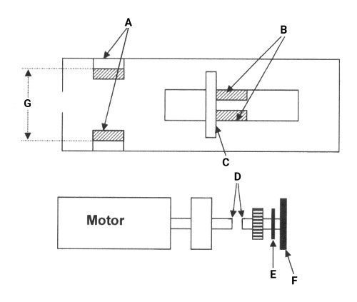
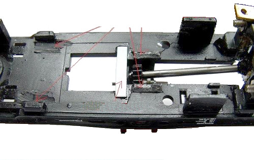
- Machine the old motor mounts "B" down from the frame with a rotary tool and grinding wheel (e.g. Dremel or alternatively cut off carefully with a pair of pliers). The back of the housing "A" must be machined down so the distance between the mounts is at least 18 mm, see "G" in the images below
- Installation of the motor:
- Connect the supplied PVC strip "C" across the frame, the front edge of the strip should be at the rear edge of the lower bearing of the transmission shaft, see previous image for strip "C"
- Apply a little grease to the spring of the coupling of the motor and insert the pinion shaft into the socket
- Before installing the pinion shaft insert the supplied nylon disc "E" in front of the sprocket and also grease the gear and axle area, see previous image for nylon disk "E"
- Assemble both together on the frame
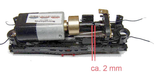
- Insert the pinion shaft into the front bearing plate and push the motor forward until the distance between the coupling and driver is approx. 1 - 2 mm, see "D" in previous image
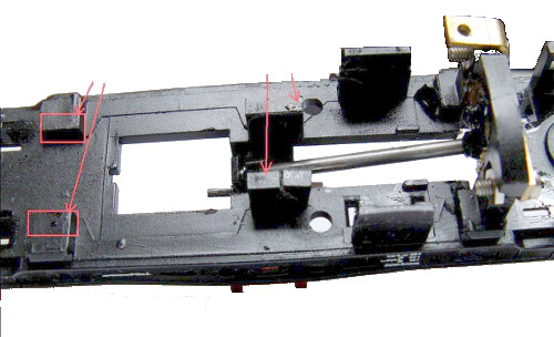
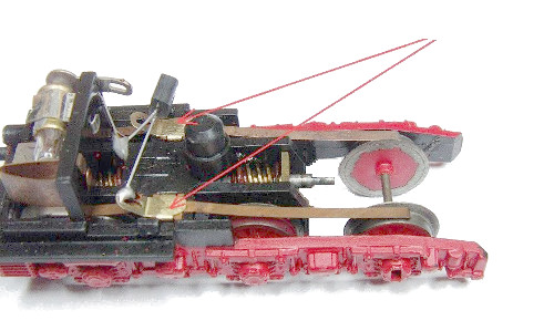
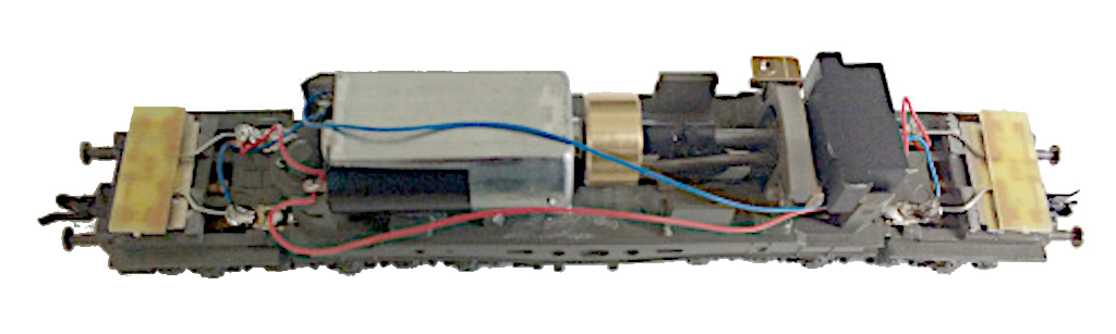
- Now align and fix the motor in the middle of the chassis and after a little bit of super-glue is applied to the PVC strip. Route the wires to the front bogie along the lower part of the motor at the same side of right side slot of the front weight.
- When the motor fixed in the middle, rotate the whole chassis and also secure the motor with additional adhesive (super-glue or two component adhesive glue) at the rear.
- Connect the supplied PVC strip "C" across the frame, the front edge of the strip should be at the rear edge of the lower bearing of the transmission shaft, see previous image for strip "C"
- Steps to install front and rear LED modules:
- Remove the diode to illuminate the lights depending on the train direction.
- Remove the filament lamps and the plastic strip carefully using a flat-nose pliers.
- In the case of Tillig models, the incandescent lamp holder and both plastic parts must be removed. Remove also the solder lug but do not remove the metal base plate itself, its secures the coupling.
- Place the LED module in the right position and adjust the connections to the proper length, peel off the adhesive pad of the LED module and fix it.
- Solder the connections to the solder lugs of the bogie.
- After the adhesive is cured:
- Pre solder the wheel contact strips
- Presoldered contact strips wheels
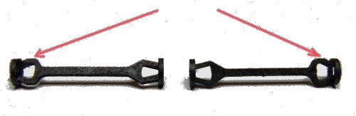
- Reinstall the bogies with the cardan shafts (larger opening in de direction of the bogie) and secure with the locking pins.
- Then solder the short wires of the motor to the soldering lugs of the rear bogie and the long wires to the soldering lugs of front bogie.
- Pre solder the wheel contact strips
- Use the slot at the right side of the front weight to route the wires through and clip the weight in its place. The rear weight is omitted.
- The refurbish ÖBB BR 1020 finished.
- Carry out a test drive:
- Secure the wires to the front bogie in the area of the flywheel with a little super glue.
- For digital operation only (DCC):
- De-solder both cables from the motor. Solder the right end of the red wire to the left the black wire of the decoder. Solder the orange and grey wire from the decoder to the motor (looking from the rear, orange to the right and grey to the left)
- Place the housing back and secure it with the screw near the pantograph.
- If the housing does not engage properly in the rear latching lugs, remove the connecting strip between the roof pantographs from the centre to the rear roof pantograph.
- For Tillig housings with screwed pantographs, unscrew the screw for the rear roof pantograph, remove the sheet metal conductor to the centre, lower the hole in the housing from the inside with a 4 - 5 mm drill to lower the screw in the housing.
- Clip the front and rear housings to the bogies.