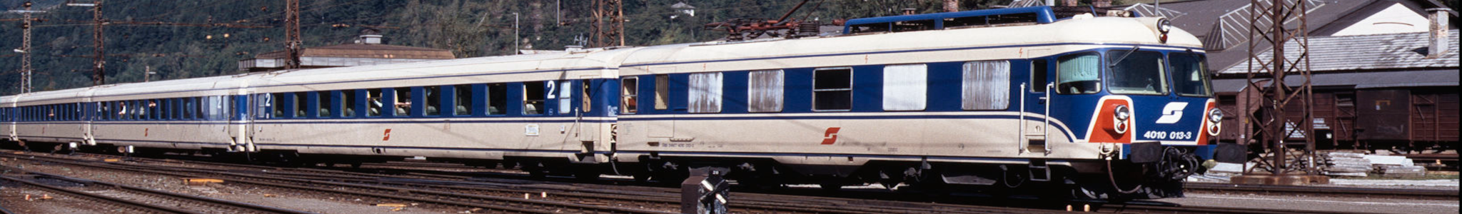
ÖBB BR 1020
Progress of requirements
Currently the CAB unit only adheres to the requirement of simulating the main switch, running a train forward and reversed, and applying the emergency brake. Requirements still to be implemented are:
- Running the micro processor at 20 MHz instead of 8 MHz
- Realistic acceleration when applying power
- Realistic deceleration when dynamic brakes are applied
- Implementation of pneumatic brakes; simulating the brake pads of the vehicles
- The motor current, the positive and negative traction force, the velocity and the pressure in the main brake line on the four gauges
- Simulation of Indusi automatic train protection, depending on the signs and signal aspects at the position of the train.
Properties actual loc
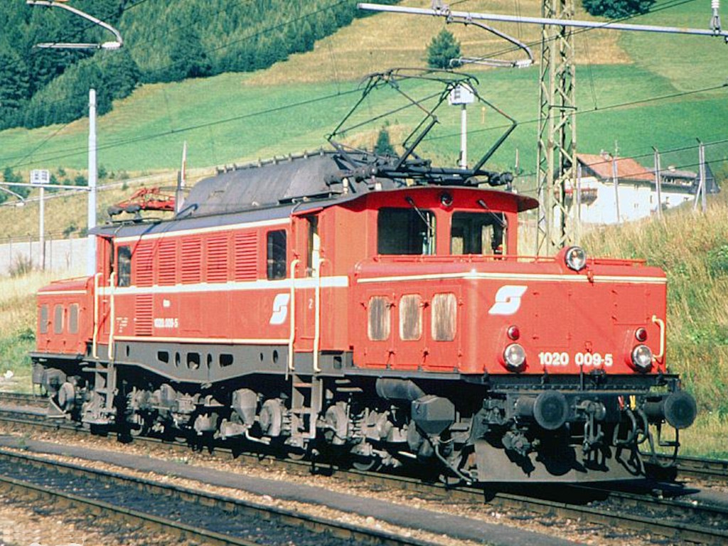
| Series: | ÖBB E 1020 |
|---|---|
| Wheel arrangement: | Co’Co’ |
| Length across buffers: | 18,600 mm |
| Top speed: | 90 km/h (25 m/s) |
| Continuous duty: | 3,000 kW at 71 km/h |
| Output per hour: | 3,300 kW with 68 km/h |
| Friction load: | 27,8 kW/t |
| Starting force: | 363 kN |
| Mass: | 118,7 ton |
Cab stand ÖBB E1020
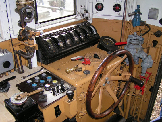
Operation:
- Initial steps
- Raise the pantograph (Not present).
- Turn the main switch (Main Switch).
- Optionally, before driving activate the fan (Not present).
- Driving
- Bring all three brakes (one brake is not present and one is incorporated in throttle wheel) the forward position.
- Set the engine traction by throttle wheel (throttle/brake wheel).
- Change of direction
- The direction of travel can be changed only when the locomotive stops.
- Change the drive direction lever (G).
Cab stand DB E94
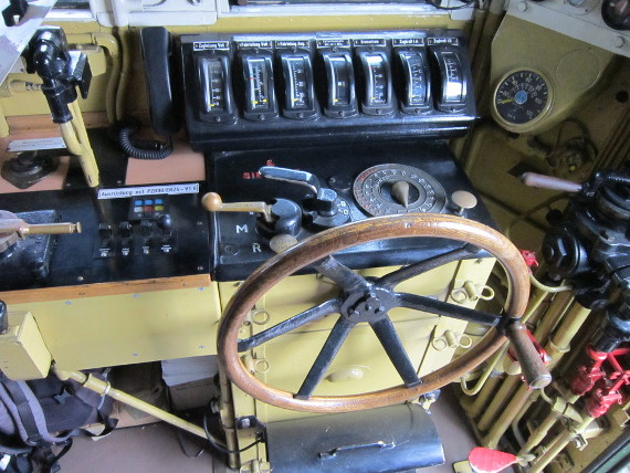
The DC brake of the German loc series E94, the equivalent of the ÖBB E1020, has been removed by the DB.
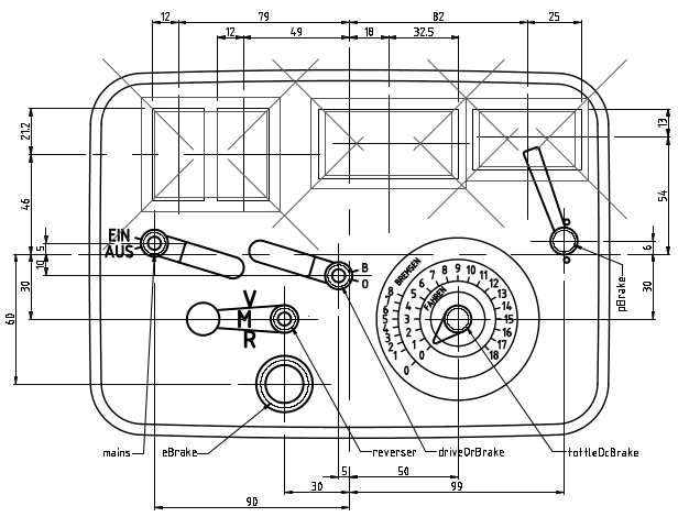
Model railway CAB unit ÖBB BR 1020
The cab unit to run the ÖBB BR 1020 on the model railway is proposed as shown in the figure below.
The analogue meters at the top of the unit have the designations from left to right:;
- the motor current;
- the positive and negative traction force;
- the velocity;
- the pressure in the main brake line.
Schematic diagram CAB unit ÖBB BR 1020
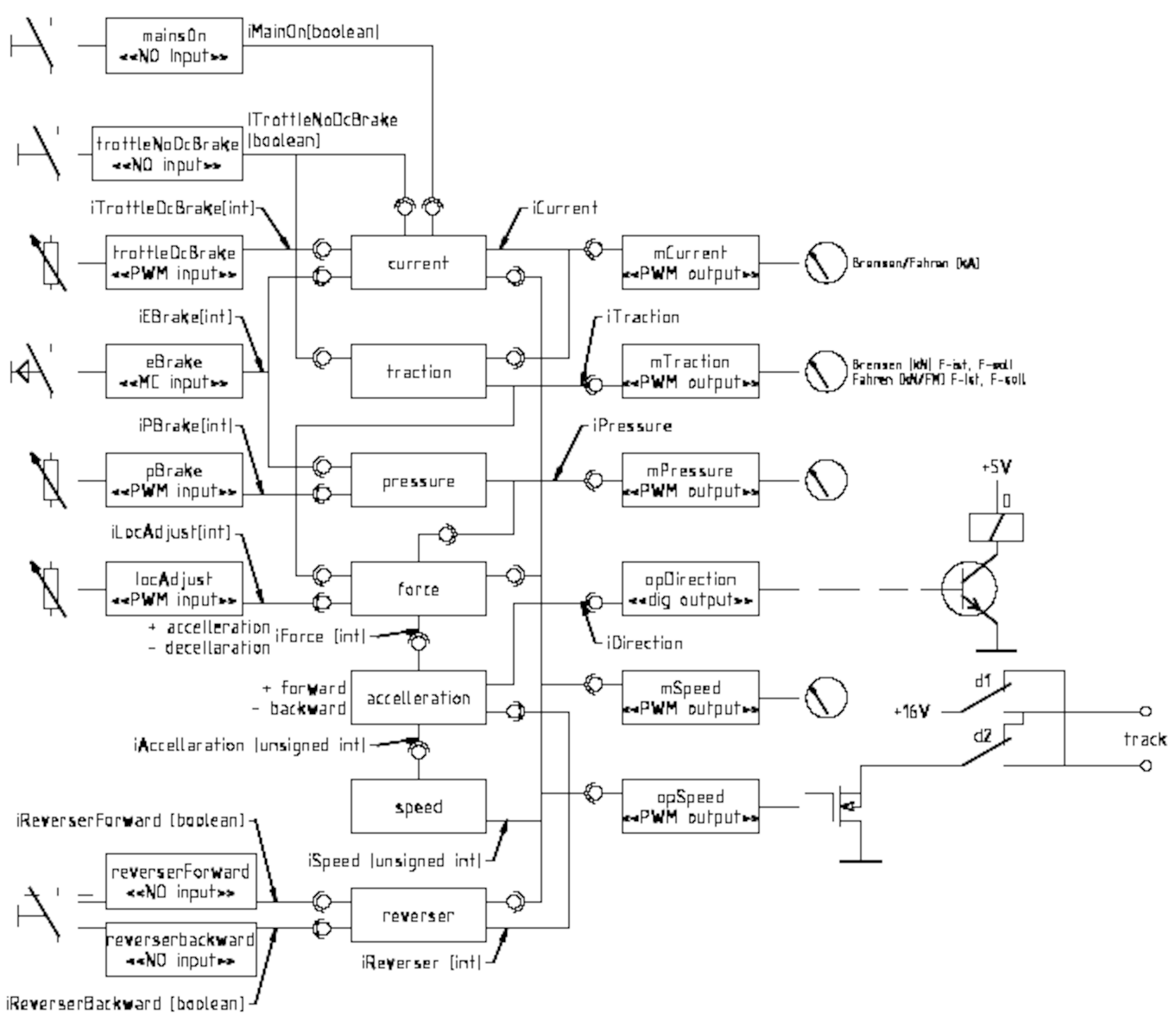
The drawing of the micro controller for the model cab stand is depicted in the following drawing. At this stage only the traction control is present. The ATP (Indusi) will follow later.
An ACT type integrated circuit is employed for IC2 which provides a output current of 24mA. The purpose is to convert the forward (pin 19), backward (pin 4) direction and PWM velocity commands (16) in a PWM traction command for either the forward or backward direction of the train. This prevents the forward and backward PWM simultaneously and damaging the components of the Command and Control system.
The potentiometer R3 is for future use to allow for speed adjustment depending on the controlled type of self propelled vehicle. However another control may be used like a multi position switch with resistors for each type of self propelled vehicles.
The purpose of the capacitors C7 to C10 is to prevent undesired movement of the meter needles of A1 to A4. The value will be determined experimentally if needed at all.
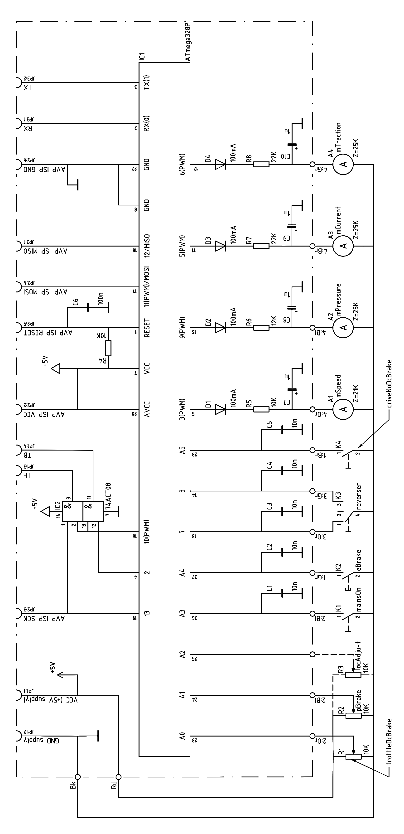
Spare ports ATmega328 for future use are shown in the table below.
| Pin No. | Designation |
|---|---|
| 4 | PD2 |
| 6 | PD4 |
| 9 | PB6(Xtal1) |
| 10 | PB7(Xtal2) |
| 17 | PB3(MOSI) |
| 18 | PB4(MISO) |
Part list for CAB unit ÖBB BR 1020
| ID | Component | Properties | Pcs. |
|---|---|---|---|
| A1 | Analogue voltmeter | 1 | |
| A2 | Analogue voltmeter | 1 | |
| A3, A4 | Analogue voltmeter | I=230µA | 2 |
| C1…C5 | Ceramic capacitor 10 nF 4.2 x 25mm TANCAP | 50V, 20 % | 5 |
| C6 | Ceramic capacitor 100 nF 4.2 x 25 mm TANCAP |
50V, 20% |
1 |
| C8…C10 | Tantalum capacitor 1 µF | 4 | |
|
D1…D4 |
TC-1N4007 Si-rectifier diode DO-204AL or 1N4001 |
1A, 1000V UF= 1.1V |
4 |
| IC1 | ATmega328P-PU micro-controller PDIP-28 | I/O=23 | 1 |
| IC2 | CD74ACT08E AND-Gate PDIP-14 | IO=24mA | 1 |
| K1, K4 | Rotary switch, 2 positions, make contacts |
|
2 |
| K2 | Push button switch, auto return, make contact |
|
1 |
| K3 | Rotary switch, 3 positions, make contacts |
|
1 |
| R1, R2 | Potentiometer 10 kΩ, linear | ¼W, 5% | 2 |
| R3 | For future use | ¼W, 5% | 0 |
| R4, R5 | Carbon film resistor 10 kΩ, 0207 (axial) | ¼W, 5% | 2 |
| R6 | Carbon film resistor 12 kΩ, 0207 (axial) | ¼W, 5% | 1 |
| R4, R5 | Carbon film resistor 22 kΩ, 0207 (axial) | ¼W, 5% | 2 |
| X1 | DIL socket, 7.62 mm, 18 pole |
Pitch 2.54 mm |
1 |
| X2 | DIL socket, 7.62 mm, 14 pole |
Pitch 2.54 mm |
1 |
| X3 | Point pitch hard-paper PCB 160x100mm | Pitch 2.54 mm | 1 |
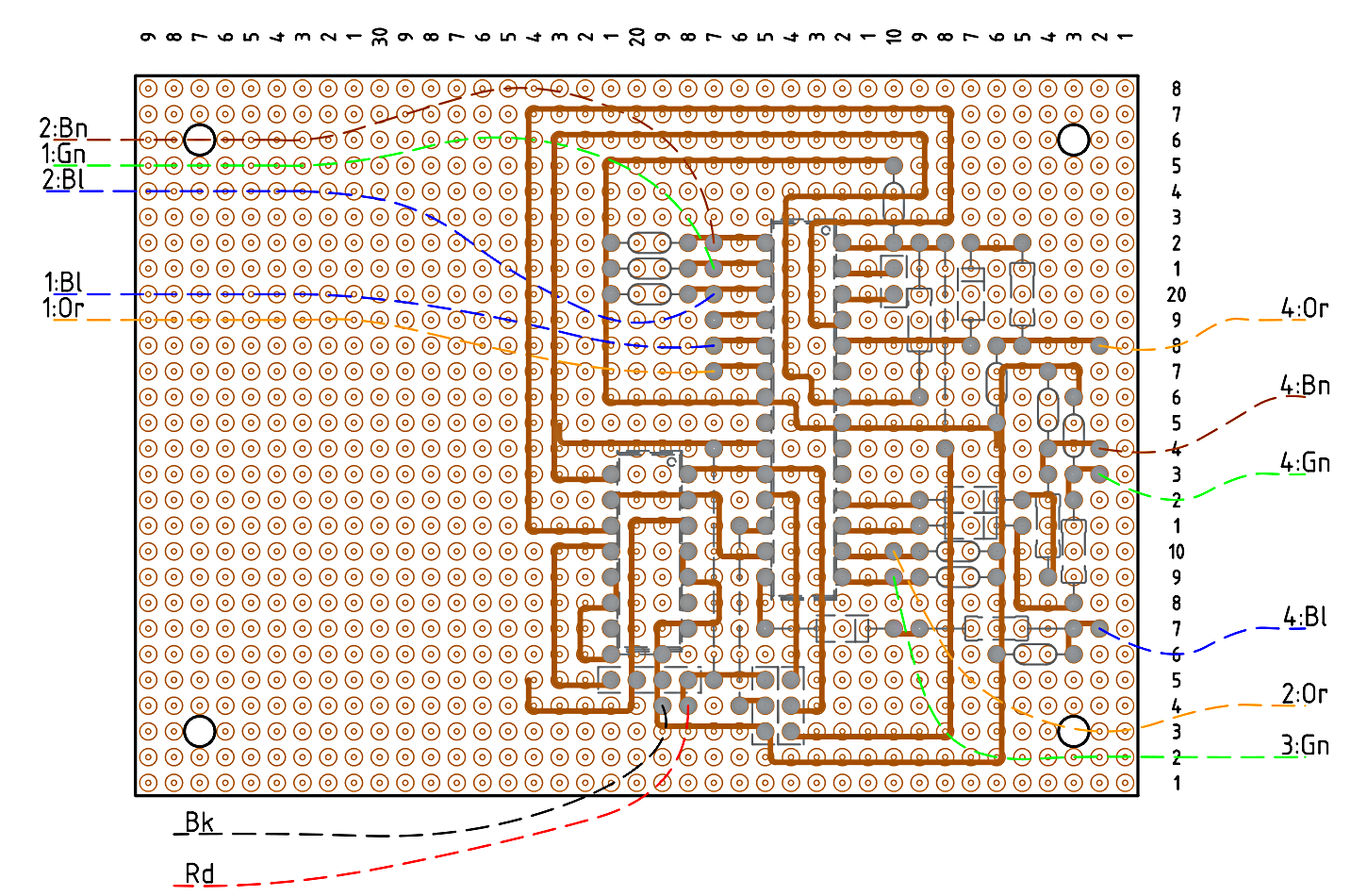
Printed circuit board CAB unit ÖBB BR 1020
The printed circuit board (PCB) will be equipped with IC feet to make IC swappable. The location of the PCB tracks allow for two resistors in case IC2 is replaced by a AND gate open collector type, see PCB Component side below.
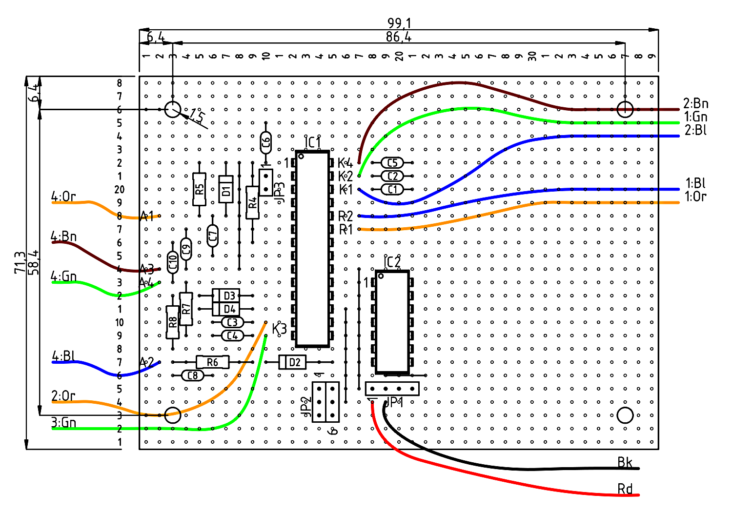
The copper track side with round copper pads is shown below. The pads are connected with bare tinned wire of 0.4mm diameter. The dashed lines are of the parts at the other side of the PCB, as shown below.
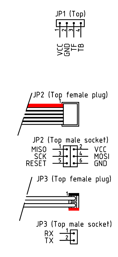
The designation of the pins of the male sockets is shown in the next figure.
Interface diagram CAB unit ÖBB BR 1020
The interface diagram between the software components is shown below.
Main loop CAB unit ÖBB BR 1020
The program embedded in the micro controller with the CAB unit for the ÖBB BR 1020 entails a continuous main loop which reads the inputs, evaluates these operates the outputs this to the appropriate traction amplifier for running a train.
Enforce full stop ÖBB BR 1020
The user case diagram to enforce full stop with the CAB unit for the ÖBB BR 1020.
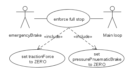
Table with use case to enforce full stop of the CAB unit for the ÖBB BR 1020.
| Use case: | Enforce full stop | Use case no.: | CAB ÖBB E1020 - | |
|---|---|---|---|---|
| Revision date: | 2014.08.15 | Revision no.: | 001 | |
| Enforces a full stop by terminating the voltage to the track and set the conditions as if an emergency brake command has been applied. | ||||
| Priority customer: | N/A | |||
| Primary actor: | Emergency brake lever (iBrake) | |||
| Secondary actors: | N/A | |||
| Preconditions: | None | |||
| Result: | Success: | Train stops immediately. | ||
| Failure: | N/A | |||
| Post conditions: |
Inability to move trein (iEBrake = 1;). |
|||
| Limitations: | None | |||
| Assumptions: | None | |||
| Trigger: | Moving the emergency lever to ON (iEBrake = 1;) | |||
| Main scenario: |
1 - Turn the emergency brake leaver to on (iEBrake = 1;) 2 - Set the lock to prevent to move the train (eBrakeLock = 1;). 3 - Set the traction off (traction = 0;) 4 - Release all the pressure of the main brake system (pressure = 0;) |
|||
| Extensions: | N/A | |||
| Source: | N/A | |||
| Author: | Roelf Koerts | |||
| Checked by: |

|
|||
Release emergency brake ÖBB BR 1020
Releases the emergency brake if the train has stopped i.e. the velocity is ZERO and also the other conditions stated below are met. The conditions also apply to allow the train to run after a full stop. The user case diagram to release emergency brake with the CAB unit for the ÖBB BR 1020 is as follows.

Table with the use case to release emergency brake with the CAB unit for the ÖBB BR 1020.
| Use case: | Release emergency brake | Use case no.: | CAB ÖBB E1020 - | |
|---|---|---|---|---|
| Revision date: | Revision no.: | 000 | ||
| Description: | Releases the lock to prevent traction and to release the main brake | |||
| Priority customer: | N/A | |||
| Primary actor: | Emergency brake lever (iBrake) | |||
| Secondary actors: | N/A | |||
| Preconditions: |
Lock to prevent to move the train is set (eBrakeLock = 1;) |
|||
| Result: | Success: | The lock to move the train is disabled. | ||
| Failure: |
|
|||
| Post conditions: |
Lock to prevent to move the train is unset (eBrakeLock = 0;) The pressure for the main brakes will be restored according to the position of the main brake lever. The traction remains of until the lever of the throttle is set to 0 |
|||
| Limitations: | None | |||
| Assumptions: | None | |||
| Trigger: |
Moving the emergency lever to OFF (iEBrake = 0;) |
|||
| Main scenario: |
1 - Turn the emergency brake leaver to OFF (iEBrake = 0;) 2 - Unset the lock to prevent to move the train (eBrakeLock = 0;). |
|||
| Extensions: |
2a - The speed of the train is not zero 2a1 - The lock to prevent to move the train remains set (eBrakeLock = 1;). |
|||
| Source: | N/A | |||
| Author: |
Roelf Koerts |
|||
| Checked by: |
|
|||
Turn mains on ÖBB BR 1020
The use case diagram to turn the power on of the ÖBB BR 1020 with its CAB unit.
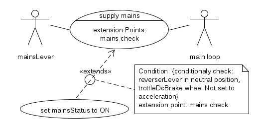
Table with the use case to turn the mains on of the ÖBB BR 1020 with its CAB unit.
| Use case: | Turn mains on | Use case no.: | CAB ÖBB E1020 - | |
|---|---|---|---|---|
| Revision date: | Revision no.: | 000 | ||
| Description: | Turns on the power for all systems | |||
| Priority customer: | N/A | |||
| Primary actor: | Mains lever | |||
| Secondary actors: | None | |||
| Preconditions: |
Reverser lever in neutral reposition (iReverserBackward==0 & iForwardBackward==0) and throttle DC wheel set to ZERO (iThrottle == 0) and Mains lever must be set to OFF (iMainsOn==0) |
|||
| Result: | Success: | All systems operational | ||
| Failure: | No systems operational | |||
| Postconditions: |
|
|||
| Limitations: |
|
|||
| Assumptions: |
|
|||
| Trigger: |
|
|||
| Main scenario: |
1 - Turn the mains lever to ON (iMainsOn = 1;) 2 - Set mains on (mainsOn=1;). |
|||
| Extensions: | 1a - Reverser lever not in neutral reposition (iReverserBackward==1 | iForwardBackward==1) and throttle DC wheel not set to ZERO (iThrottle > 0) | |||
| Source: |
|
|||
| Author: |
|
|||
| Checked by: |
|
|||
Change driving direction ÖBB BR 1020
The user case diagram to change the direction of the ÖBB BR 1020 with its CAB unit.
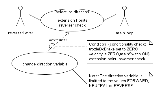
Table with the user case to change the direction of the ÖBB BR 1020 with its CAB unit.
| Use case: | Change driving direction of loc | Use case no.: | CAB ÖBB E1020 - | |
|---|---|---|---|---|
| Revision date: | Revision no.: | 000 | ||
| Description: |
|
|||
| Priority customer: | N/A | |||
| Primary actor: |
|
|||
| Secondary actors: |
|
|||
| Pre conditions: |
|
|||
| Result: | Success: |
|
||
| Failure: |
|
|||
| Post conditions: |
|
|||
| Limitations: |
|
|||
| Assumptions: |
|
|||
| Trigger: |
|
|||
| Main scenario: |
|
|||
| Extensions: |
|
|||
| Source: |
|
|||
| Author: |
|
|||
| Checked by: |
|
|||
Enable DC brake ÖBB BR 1020
Enable DC brake use case diagram of the ÖBB BR 1020 with its CAB unit.
Table with the use case to Enable DC brake of the ÖBB BR 1020 with its CAB unit.
| Use case: | Enable DC brake | Use case no.: | CAB ÖBB E1020 - | |
|---|---|---|---|---|
| Revision date: | 2014-10-07 | Revision no.: | 000 | |
| Description: | ThrottleDcBrake lever (iThrottleNoDcBrake) | |||
| Priority customer: | N/A | |||
| Primary actor: |
|
|||
| Secondary actors: |
|
|||
| Preconditions: |
The Throttle/DC Brake lever must be in the in the 'O' position |
|||
| Result: | Success: |
|
||
| Failure: |
|
|||
| Post conditions: | Procoditions are set to vary the deceleration of the train with the throttle/DC brake variable power control. | |||
| Limitations: |
|
|||
| Assumptions: |
|
|||
| Trigger: |
|
|||
| Main scenario: |
1 - Set the Throttle/DC Brake lever in the 'B' position 2 - Conditions are set to vary the deceleration of the train using the throttle/DC brake variable power control. |
|||
| Extensions: |
|
|||
| Source: |
|
|||
| Author: |
|
|||
| Checked by: |
|
|||
Activate throttle ÖBB BR 1020
Enable throttle use case diagram of the ÖBB BR 1020 with its CAB unit.
Table with the use case Enable throttle of the ÖBB BR 1020 with its CAB unit.
| Use case: | Activate throttle | Use case no.: | CAB ÖBB E1020 - | |
|---|---|---|---|---|
| Revision date: | 2014-10-07 | Revision no.: | 000 | |
| Description: |
Allows to vary acceleration of the train with electric power. |
|||
| Priority customer: | N/A | |||
| Primary actor: | Driver | |||
| Secondary actors: |
|
|||
| Preconditions: | The Throttle/DC Brake lever must be in the in the 'B' position | |||
| Result: | Success: |
|
||
| Failure: |
|
|||
| Post conditions: |
Precondition is set to vary the acceleration of the train with the throttle/DC brake variable power control. |
|||
| Limitations: |
|
|||
| Assumptions: |
|
|||
| Trigger: |
|
|||
| Main scenario: |
1 - Set the Throttle/DC Brake lever in the 'O' position 2 - Conditions are set to vary acceleration of the train with electric power. |
|||
| Extensions: |
|
|||
| Source: |
|
|||
| Author: |
|
|||
| Checked by: |
|
|||
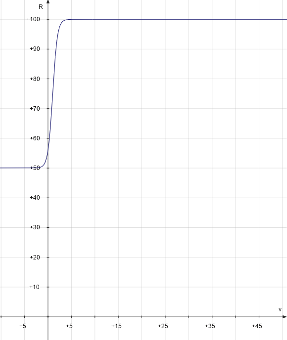
Trottle or electric brace ÖBB BR 1020
Here the use case diagram depicts the control of the throttle or DC brake to change the acceleration.
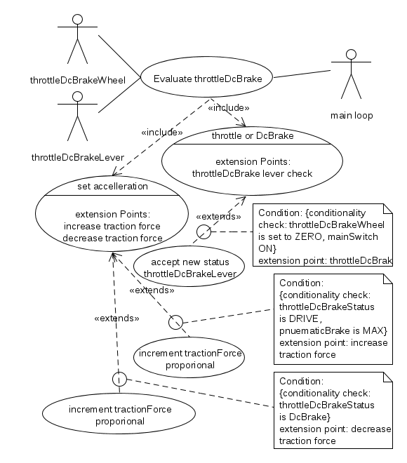
The use case table entails the the control of the throttle or DC brake to change the acceleration.
| Use case: | Throttle or electric brace force | Use case no.: | CAB ÖBB E1020 - | |
|---|---|---|---|---|
| Revision date: | Revision no.: | 000 | ||
| Description: |
|
|||
| Priority customer: | N/A | |||
| Primary actor: |
|
|||
| Secondary actors: |
|
|||
| Preconditions: |
|
|||
| Result: | Success: |
|
||
| Failure: |
|
|||
| Post conditions: |
|
|||
| Limitations: |
|
|||
| Assumptions: |
|
|||
| Trigger: |
|
|||
| Main scenario: |
|
|||
| Extensions: |
|
|||
| Source: |
|
|||
| Author: |
|
|||
| Checked by: |
|
|||
Pneumatic brake
The pneumatic brake consist of the brake shoes of all wheels of the train. When the pressure is at its maximum the brakes are released and when the pressure is released it will apply the brakes. The operation of the pneumatic brake is as follows.
- If the lever is in the forward position the pressure increases
- If the lever is in the middle position the pressure remains constant
- If the lever in the backward position the the pressure decreases.
Below the user case diagram of the pneumatic brake.
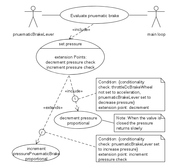
Below is the use case table of the pneumatic brake.
| Use case: | Pneumatic brake | Use case no.: | CAB ÖBB E1020 - | |
|---|---|---|---|---|
| Revision date: | Revision no.: | 000 | ||
| Description: |
|
|||
| Priority customer: | N/A | |||
| Primary actor: |
|
|||
| Secondary actors: |
|
|||
| Preconditions: |
|
|||
| Result: | Success: |
|
||
| Failure: |
|
|||
| Post conditions: |
|
|||
| Limitations: |
|
|||
| Assumptions: |
|
|||
| Trigger: |
|
|||
| Main scenario: |
|
|||
| Extensions: |
|
|||
| Source: |
|
|||
| Author: |
|
|||
| Checked by: |
|
|||