


Dual plus and minus 15V power supply
Principle
The voltage output of this power supply is 15V, because this is the maximum allowed voltage for TT-scale self propelled vehicles. A plus 15 and minus 15 voltage output is provided to simplify the traction control circuitry with transistors for speed and direction. This also applies to the point motors. The average current drawn by a self propelled vehicle is 500mA. My requirement is to run six of these vehicles to run simultaneously at maximum speed. This means that the 'Dual plus and minus 15V power supply' should deliver a stable voltage at currents up to 3A. I had two worn down electric blankets laying around with each a transformer of two outputs of 18 VAC 50VA. These transformers were suitable for a conventional power supply with the required voltages en power. Next to these transformers I used LM350 and LT1033 voltage regulator ICs. Both ICs provide a voltage regulator, a power output stage and a built-in overload protection which activates at 30 watts of power dissipation. The circuit for these ICs allows the output voltage to be varied from 1.25 volts to 18 volts. The voltage output is set by connecting the “adj” pin of the IC to the voltage divider made of the two potentiometer R1 and R2 (Rpot) and the resistors R3 and R4 at the output (Rout). The output voltage is calculated using the following formula:
Where the potentiometer R1 and R2 values are between 0 and 5 kΩ. The diodes D5 and D6 serves as protection for the regulator IC when the IC output is turned off.
The resistor R3 and R4 are 270Ω. This ensures that the minimal load current for the IC (around 3.4mA) is high enough to maintain a good performance. The circuit diagram is:
The part list with electronic devices is shown below.
| ID | Component | Properties | Oty |
|---|---|---|---|
| C1, C2, C5, C6 | Ceramic capacitor 100nF | 50V, 20% | 4pcs |
| C3, C4 | Elco 4700µF | 35V, 20% | 2pcs |
| C7, C8 | Elco 47µF | 63V, 20% | 2pcs |
| D1 - D4 | Diode BY550-800, case: DO-201AD | 5A, 800V | 4pcs |
| D5 - D8 | Diode 1N4001 (or 1N4007) | 1A, 50V | 4pcs |
| IC1 | Regulator LM350T, case TO-220 | 3A, 33V | 1pcs |
| IC2 | Regulator LT1033 CT, case TO-220 | 3A, –32V | 1pcs |
| F1 | Micro fuse 5x20mm | 250V, 0.5 A | 1pcs |
| R1, R2 | Potentiometer 5KΩ | 0.2W, 20% | 2pcs |
| R3, R4 | Resistor 270Ω axial | 0.25W, 20% | 2pcs |
| T1, T2 | Transformer 250/18.6VAC | 50VA | 2pcs |
| IC1,2 | Fin heat sink SK 482 100 SA + 4x THFU, L=100, W=33, H=35mm | 3.25°C/W | 1pcs |
| IC1,2 | Thermally conductive film 0.25mm folie 70/50 TO-220 | 0.44°C/W | 1pcs |
The original value of the resistors R1 and R2 of 2K5 did not deliver the required maximum voltage of 15V. However a parallel resistor R3 of 3K allowed for the right voltage, see table below.
|
R2 [Ω] |
R3 [Ω] |
Rv [Ω] |
Vout,max [V]. |
|---|---|---|---|
| 2K5 | N/A | 2K5 | 24.1 |
| 10K | 2K | 22.0 | |
| 1K5 | 940 | 11.0 | |
| 3K | 1K36 | 15.6 |
The above resistor values and voltages are experimentally determined without load. This is sufficient for testing tracks with only one train. However this must be retested when the model railway is finished and all trains are running simultaneously.
Heat sink LM350T or LT1033CT
To select the right heat sink you need to know its thermal resistance θ, which is expressed in °C/W or K/W. As these are relative units the value for both are the same.
The properties of the heat sink can be calculated based on the maximum power dissipation of the component getting hot, the maximum ambient air temperature and the thermal resistance in between.
The calculation for the power dissipation Pdiss of a switching regulators like LM350T or LT1033CT is shown below. The input Iin and output current Iout can be considered equal.
Efficiency is then:
The power dissipation Pdiss equals the heat source dissipation Q:
If you use the adjustable regulator without a heat sync you have to take the thermal resistance between junction where the heat occurs, and ambient air θJA into account. This can be obtained from the data sheets. The LM350T or LT1033CT comes in two different cases TO-3, a metal can package, and a TO-220, a plastic case.
The maximum operating junction temperature TJmax is for a TO-3 and TO 220 package 125°C.
The ambient air temperature TA is assumed to be 35°C.
Heat dissipation TO-3 package LM350T or LT1033CT
For the TO-3 the thermal resistance between the junction to ambient air is θJA is typical 35°C/W.
This means that the junction temperature TJ is:
This is much higher than the maximum allowed junction temperature TJmax of 125°C. The calculation of the required heat sink has been waived because the LM350T or LT1033CT in a TO-3 package and a heat sink is far more expensive than a TO-220 package with heat sink.
Heat sink TO-220 package LM350T or LT1033CT
A LM350T or LT1033CT in a TO-220 package requires a heat sink due to its junction to ambient thermal resistance θJA of 50°C/W . The formula to calculate the heat sink is:
From the data sheets the junction and the case θJC is typical 3°C/W. Thus the required thermal resistance between of the heat sink θHA needs to be equal or lower than:
Where:
| TJ | The maximum operating junction temperature: normally 125°C |
| TA | Ambient temperature: normally 35°C |
| Q | Heat source dissipation: 9W |
| θJC | Thermal resistance of a LM350T or LT1033CT in a TO-220 package between the junction and the case |
| θF | Thermal resistance of the 70/50 thermally conductive film of 0.25mm: 0.44°C/W |
Conclusion: The heat sink of θJA=3.25°C/W in the part list above has ample thermal resistance.
Printed circuit board
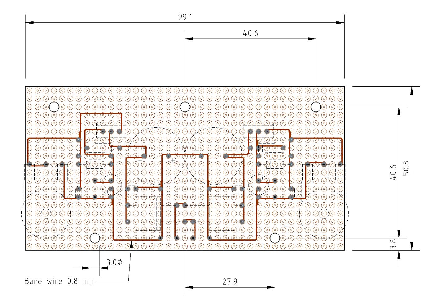
The type of printed circuit board (PCB) for the dual plus and minus 15V power supply is a point pitch hard-paper board with copper (Cu) coating and a grid size of 2.54 mm .
The component side of the PCB:
The pin-out of the LM 350 and LT1033 is depicted in the figure below.
The following image shows the copper side op the PCB. Bare wires of 0.8mm are soldered between point pitches to allow for 3A of current.
Below is the parts list for the Printed circuit board.
| ID | Component | Properties | Qty |
|---|---|---|---|
| X1 | Point pitch hard-paper PCB 160x100mm | Pitch 2.54mm | 1pcs |
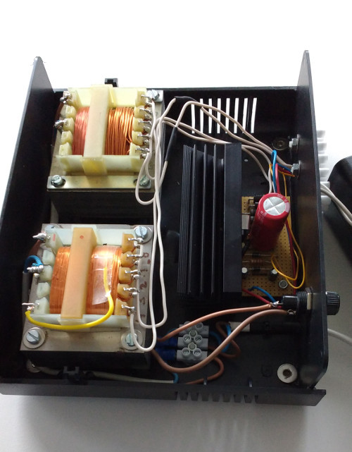
Enclosure dual plus and minus 15V power supply
The case and internals is depicted in the figure below.
Below is the parts list. The current rating for the DC connectors and wires are 6A.
| ID | Component | Properties | Qty |
|---|---|---|---|
| S1 | Tru Components TC-R13-66A-02 Rocker switch, off/on locked | 6A, 250VAC | 1pcs |
| X2 | Nut spacers 15mm M4 | Messing | 8pcs |
| X3 | Spacer 5mm diam M3 |
Polystyrene |
8pcs |
| X5 | Encloser 180x205x70mm | Polystyrene | 1pcs |
| X6 | Fuse holder for 5x20 fuse |
|
3pcs |
| X7 | Plastic screws M3 - 20mm | Bag of 10 | 1pcs |
| X8 | Plastic screws M4 - 20mm | Bag of 10 | 1pcs |
| X9 | Econ Connect AK6SW Pole terminal red 16A | d=6,3 | 1pcs |
| X10 | Econ Connect AK6SW Pole terminal blue 16A |
d=6,3 |
1pcs |
| X11 | Econ Connect AK6SW Pole terminal black 16A |
d=6,3 |
1pcs |
| X12 | Banana plug, straight Schnepp 4 mm rood |
Stift-Ø: 4 mm |
1pcs |
| X13 | Banana plug, straight Schnepp 4 mm blauw |
Stift-Ø: 4 mm |
1pcs |
| X14 | Banana plug, straight Schnepp 4 mm zwart |
Stift-Ø: 4 mm |
1pcs |