Page updated on 15 May 2024

Photo of me
My banner

Supply

This web page is about designing and building two power supplies for my model railway. One of the power supplies is a Dual plus and minus 15V power supply for the traction current for self propelled vehicles, to operate points of turnouts and to operate decoupler solenoids. The other power supply is a 'Logic 5V and miscellaneous 5V power supply' for logic circuits, respectively train detection and miscellaneous devices like line site signals, houses etc.

Dual plus and minus 15V power supply

Principle

The voltage output of this power supply is 15V, because this is the maximum allowed voltage for TT-scale self propelled vehicles. A plus 15 and minus 15 voltage output is provided to simplify the traction control circuitry with transistors for speed and direction. This also applies to the point motors. The average current drawn by a self propelled vehicle is 500mA. My requirement is to run six of these vehicles to run simultaneously at maximum speed. This means that the 'Dual plus and minus 15V power supply' should deliver a stable voltage at currents up to 3A. I had two worn down electric blankets laying around with each a transformer of two outputs of 18 VAC 50VA. These transformers were suitable for a conventional power supply with the required voltages en power. Next to these transformers I used LM350 and LT1033 voltage regulator ICs. Both ICs provide a voltage regulator, a power output stage and a built-in overload protection which activates at 30 watts of power dissipation. The circuit for these ICs allows the output voltage to be varied from 1.25 volts to 18 volts. The voltage output is set by connecting the “adj” pin of the IC to the voltage divider made of the two potentiometer R1 and R2 (Rpot) and the resistors R3 and R4 at the output (Rout). The output voltage is calculated using the following formula:

V out = 1.25 V ( 1 + R pot R out ) V _ out = 1.25 V ({ 1 + { R_pot over R_out } } )

Where the potentiometer R1 and R2 values are between 0 and 5 kΩ. The diodes D5 and D6 serves as protection for the regulator IC when the IC output is turned off.
The resistor R3 and R4 are 270Ω. This ensures that the minimal load current for the IC (around 3.4mA) is high enough to maintain a good performance. The circuit diagram is:

Dual voltage power supply circuit diagram

The part list with electronic devices is shown below.

ID Component Properties Oty
C1, C2, C5, C6 Ceramic capacitor 100nF 50V, 20% 4pcs
C3, C4 Elco 4700µF 35V, 20% 2pcs
C7, C8 Elco 47µF 63V, 20% 2pcs
D1 - D4 Diode BY550-800, case: DO-201AD 5A, 800V 4pcs
D5 - D8 Diode 1N4001 (or 1N4007) 1A, 50V 4pcs
IC1 Regulator LM350T, case TO-220 3A, 33V 1pcs
IC2 Regulator LT1033 CT, case TO-220 3A, –32V 1pcs
F1 Micro fuse 5x20mm 250V, 0.5 A 1pcs
R1, R2 Potentiometer 5KΩ 0.2W, 20% 2pcs
R3, R4 Resistor 270Ω axial 0.25W, 20% 2pcs
T1, T2 Transformer 250/18.6VAC 50VA 2pcs
IC1,2 Fin heat sink SK 482 100 SA + 4x THFU, L=100, W=33, H=35mm 3.25°C/W 1pcs
IC1,2 Thermally conductive film 0.25mm folie 70/50 TO-220 0.44°C/W 1pcs

The original value of the resistors R1 and R2 of 2K5 did not deliver the required maximum voltage of 15V. However a parallel resistor R3 of 3K allowed for the right voltage, see table below.

R2
[Ω]
R3
[Ω]
Rv
[Ω]
Vout,max
[V].
2K5 N/A 2K5 24.1
10K 2K 22.0
1K5 940 11.0
3K 1K36 15.6

The above resistor values and voltages are experimentally determined without load. This is sufficient for testing tracks with only one train. However this must be retested when the model railway is finished and all trains are running simultaneously.

Heat sink LM350T or LT1033CT

To select the right heat sink you need to know its thermal resistance θ, which is expressed in °C/W or K/W. As these are relative units the value for both are the same.

The properties of the heat sink can be calculated based on the maximum power dissipation of the component getting hot, the maximum ambient air temperature and the thermal resistance in between.

The calculation for the power dissipation Pdiss of a switching regulators like LM350T or LT1033CT is shown below. The input Iin and output current Iout can be considered equal.

P diss = P in P out P diss = U in I in U out I out P diss = 18 3 15 3 P diss = 54 45 P diss = 9 ° C / W matrix{ alignr P_{diss} # {}={} # alignl P_"in" – P_out ## alignr P_{diss} # {}={} # alignl U_"in" I_"in" - U_out I_out ## alignr P_{diss} # {}={} # alignl 18 cdot 3 - 15 cdot 3 ## alignr P_{diss} # {}={} # alignl 54 – 45 ## alignr P_{diss} # {}={} # alignl 9{°C/W} }

Efficiency is then:

ƞ = P out P in ƞ = 45 54 ƞ = 0.83 matrix{ alignr ƞ # {}={} # alignl P_out over P_"in" ## alignr ƞ # {}={} # alignl 45 over54 ## alignr ƞ # {}={} # alignl 0.83 }

The power dissipation Pdiss equals the heat source dissipation Q:

Q = P diss Q = 9 W matrix{ alignr Q # {}={} # alignl P_{diss} ## alignr Q # {}={} # alignl 9W }

If you use the adjustable regulator without a heat sync you have to take the thermal resistance between junction where the heat occurs, and ambient air θJA into account. This can be obtained from the data sheets. The LM350T or LT1033CT comes in two different cases TO-3, a metal can package, and a TO-220, a plastic case.

The maximum operating junction temperature TJmax is for a TO-3 and TO 220 package 125°C.

The ambient air temperature TA is assumed to be 35°C.

Heat dissipation TO-3 package LM350T or LT1033CT

For the TO-3 the thermal resistance between the junction to ambient air is θJA is typical 35°C/W.

This means that the junction temperature TJ is:

T J = T A + θ JA Q T J = 35 + 35 9 T J = 350 ° C matrix{ alignr T_J # {}={} # alignl T_A + θ_{JA}Q ## alignr T_J # {}={} # alignl 35 + 35 cdot 9 ## alignr T_J # {}={} # alignl 350°C }

This is much higher than the maximum allowed junction temperature TJmax of 125°C. The calculation of the required heat sink has been waived because the LM350T or LT1033CT in a TO-3 package and a heat sink is far more expensive than a TO-220 package with heat sink.

Heat sink TO-220 package LM350T or LT1033CT

A LM350T or LT1033CT in a TO-220 package requires a heat sink due to its junction to ambient thermal resistance θJA of 50°C/W . The formula to calculate the heat sink is:

θ HA = T J T A Q θ JC θ F θ_{HA}={{T_J-T_A} over Q} - θ_{JC} - θ_F

From the data sheets the junction and the case θJC is typical 3°C/W. Thus the required thermal resistance between of the heat sink θHA needs to be equal or lower than:

θ HA = T J T A Q θ JC θ F θ HA = 125 35 9 3 0.44 θ HA = 6.56 ° C / W matrix{ alignr θ_{HA} # {}={} # alignl {{T_J-T_A} over {alignc Q}} - θ_{JC} - θ_F ## alignr θ_{HA} # {}={} # alignl {{125-35} over {alignc 9}} - 3 - 0.44 ## alignr θ_{HA} # {}={} # alignl 6.56{°C/W} }

Where:

TJ The maximum operating junction temperature: normally 125°C
TA Ambient temperature: normally 35°C
Q Heat source dissipation: 9W
θJC Thermal resistance of a LM350T or LT1033CT in a TO-220 package between the junction and the case
θF Thermal resistance of the 70/50 thermally conductive film of 0.25mm: 0.44°C/W

Conclusion: The heat sink of θJA=3.25°C/W in the part list above has ample thermal resistance.

Printed circuit board

The type of printed circuit board (PCB) for the dual plus and minus 15V power supply is a point pitch hard-paper board with copper (Cu) coating and a grid size of 2.54 mm .
The component side of the PCB:

Image with component side PCB of adjustable dual power supply van 15V_0V_-15V_3A-

The pin-out of the LM 350 and LT1033 is depicted in the figure below.

Figure with pinout LM 350Figure with pinout LT1033

The following image shows the copper side op the PCB. Bare wires of 0.8mm are soldered between point pitches to allow for 3A of current.

Image with PCB trackside of adjustable dual power supply 15V 0V -15 V_3A

Below is the parts list for the Printed circuit board.

ID Component Properties Qty
X1 Point pitch hard-paper PCB 160x100mm Pitch 2.54mm 1pcs

Enclosure dual plus and minus 15V power supply

The case and internals is depicted in the figure below.

Power supply photo

Below is the parts list. The current rating for the DC connectors and wires are 6A.

ID Component Properties Qty
S1 Tru Components TC-R13-66A-02 Rocker switch, off/on locked 6A, 250VAC 1pcs
X2 Nut spacers 15mm M4  Messing 8pcs
X3 Spacer 5mm diam M3 Polystyrene
8pcs
X5 Encloser 180x205x70mm Polystyrene 1pcs
X6 Fuse holder for 5x20 fuse
3pcs
X7 Plastic screws M3 - 20mm Bag of 10 1pcs
X8 Plastic screws M4 - 20mm Bag of 10 1pcs
X9 Econ Connect AK6SW Pole terminal red 16A d=6,3 1pcs
X10 Econ Connect AK6SW Pole terminal blue 16A d=6,3
1pcs
X11 Econ Connect AK6SW Pole terminal black 16A d=6,3
1pcs
X12 Banana plug, straight Schnepp 4 mm rood Stift-Ø: 4 mm
1pcs
X13 Banana plug, straight Schnepp 4 mm blauw Stift-Ø: 4 mm
1pcs
X14 Banana plug, straight Schnepp 4 mm zwart Stift-Ø: 4 mm
1pcs

Logic 5V and miscellaneous 5V power supply

Application switch mode power supply

This power supply provides two independent power outputs, one for logic digital circuits and one for track circuits and miscellaneous loads like illumination devices. The power supply for the track circuits and miscellaneous components is a independent unit to avoid the wrong operation of track circuits. At the other hand the power supply for logic digital components is a independent unit to avoid the faulty operation of logic digital components due to noise.

Two AC/DC switch mode power supply modules are used. They have a power rating of 7A. This is higher than required but avoids reformation of the plastic enclosure due to overheating. It is the same enclosure used for the above 'Dual plus and minus 15V power supply'.


Description components and wiring

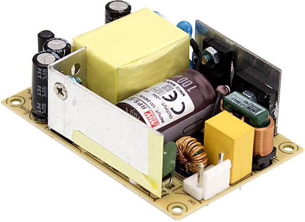
The used switch mode power supply is a Mean Well RPS-65-5 5, see image below. The price of each unit was around €17.00 in 2020.

Figure with switch mode power supply Mean Well_RPS-65-5 5.

The logic 5V and miscellaneous 5V power supply circuits have each its own mains power switch S1 resp. S2 and fuse F1 resp. F2. These and the neutral are connected to the hot side of the switch mode power supply X1 resp. X2 by a female crimp plug J1 resp. J2, see photo below.

Figure with switch mode power supply Mean Well_RPS-65-5 5.

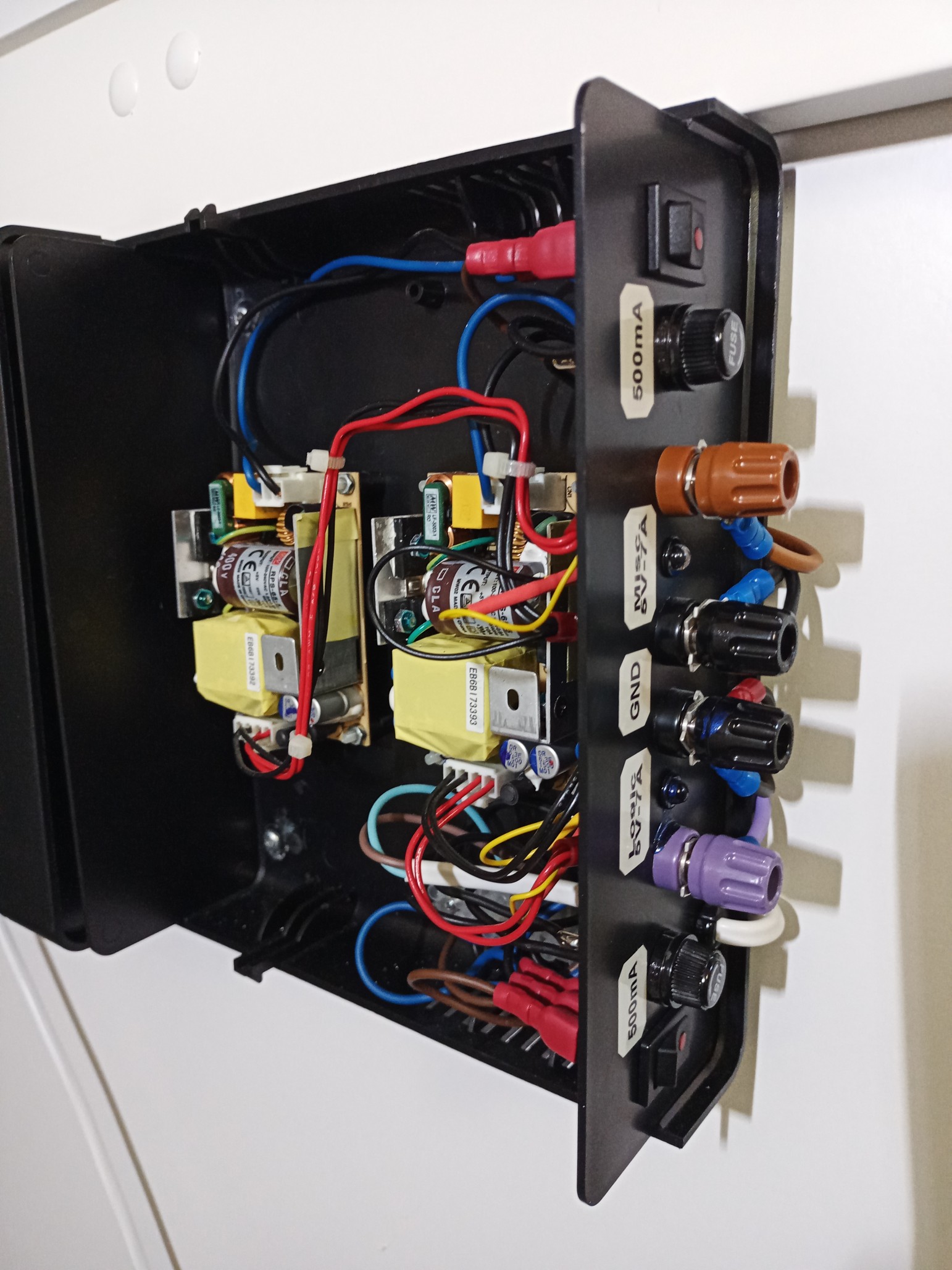
The 5VDC cold side of the switch mode power supply for logic circuits is connected to a violet pole terminal J5 and the one for miscellaneous devices to a brown pole terminal J6. The GND of each switch mode power supply is individually connected to the black pole terminals J7 resp. J8. All these 5VDC and GND wires are connected to the switch mode power supplies with 4 pole female crimp plug J3 resp. J4. The current rating for the DC connectors and wires is 22 A.
The 5VDC for logic circuits is connected via a current limiting resistor R1 to a blue LED D1. The 5VDC for miscellaneous devices is connected via a current limiting resistor R2 to a green LED D2.

Part list with components are stated below.

ID Component Properties Qty
X1, X2 AC/DC PSU module (open frame) Mean Well RPS-65-5 5, ripple(PP) 80mV, efficiency 84% 5VDC, 11A 2pcs
D1 LED wired Blue Circular 5 mm, 1150mcd, 20° 20 mA, 3.5V 1pcs
D2 LED wired Green Circular 5 mm, 1000mcd, 20° 20 mA, 2.1V 1pcs
F1, F2 TRU COMPONENTS TC-R3-12 Fuse holder Suitable for Micro fuse 5 x 20mm, 10A, 250V AC D=15mm∅ 2pcs
F1, F2 Püschel FST0,315B Micro fuse (Ø x L) 5 x 20mm, time delay 0.315A, 250V 2pcs
R1, R2 Carbon film resistor 270Ω Axial lead 0207, 0.25W, 5% Type 0207 2pcs
S1, S2 SCI Toggle switch R13-66B2-02 (250V/AC 150KR) 250VAC, 6A, 1 x Off/On latch L=19.4mm, W=13mm 2pcs
W1 GAO 6777 Current cable white 1.50m     Max. 2.5A 1pcs
W2 TRU COMPONENTS TC-SR-F21203 Strain relief Terminal Ø (max.) 5.3mm black
2pcs
J1, J2 JST VHR-3N VHR-3N Casing Series VH Number of pins: 3 Nominal current: 10A AWG #22 to #16 2pcs
J3, J4 JST VHR-4N VHR-4N Casing Series VH Number of pins: 4 Nominal current: 10A AWG #22 to #16
2pcs
J1, J2, J3, J4 JST BVH-21T-P1.1 BVH-21T-P1.1 Crimp Contact For Series VH Nominal current: 10A AWG #22 to #16 12pcs
J5 Hirschmann 35A SKS pole terminal PKI 10 A Stift-Ø: 4mm violet
M4, 35A, ~7∅
1pcs
J6 Hirschmann 35A SKS pole terminal PKI 10 A Stift-Ø: 4mm brown M4, 35A 1pcs
J7, J8 Hirschmann 35A SKS pole terminal PKI 10 A Stift-Ø: 4mm black M4, 35A
2pcs
E1 Universal enclosure 180 x 205 x 70mm Polystyrene (EPS) black
1pcs
E2 TOOLCRAFT 839971 Countersunk screws M4 - 25 mm Phillips DIN 965 plastic, polyamide 10 pc(s) Bag of 10 1pcs
E3 Spacer w/o thread M4 Polystyrene Distance 15mm 

8pcs