This webpage is states the guidelines for the layout and construction of my TT model railway.
Contents:
TT track spacings
The design concerns the stations and open lines of the Tauernbahn on my TT model railway. The drawings used for the layout of the tracks have the following scale and grid size.
Object
Property
TT track plans
Drawings
Scale
1:10
Drawings of yards and stations
Scale
1:5
Grid
Size
400 mm
Platform length
To take into account the recommended train length for Schwarzach - St Veit station and Oberfalkenstein train stop, the minimum required platform length is shown below.
Object
Property
TT track plans
Platform for local services only
Length
1000 mm
Platform suitable for main services
Length
1600 mm
Station length
The design tests in TT gauge show that it is feasible to scale down the length of a real world Schwarzach - St Veit station and Oberfalkenstein train stop. In TT, the actual length of Schwarzach - St Veit station is 12500 mm. As only 4500 m is available on my TT layout, the length of 12500 mm has to be reduced by a factor of 0.36. So the total reduction factor is 120/0.36 is 3-10-3.
The formula is:
where: lTT = the length in TT in mm lW = the real world length in mm.
Radii of curved tracks
The aim is to get the curve radii of my TT model railway as close as possible to the Tauernbahn, leaving as much space as possible for stations and other parts of the layout. Even if the radii of real railway curves are reduced to TT scale 1:120 they will not fit on my model railway.
Minimum track radii
For main tracks, the minimum track radii are based on 45 times the track spacing and the standard radii of turnouts of Tillig's Advanced Track. This provides a more realistic view of carriages on curves. The radii of local track are smaller because carriages are generally shorter.
Object
Property
TT track plan
Curved track main lines
Radius
≥ 631 mm
Curved track branch lines
Radius
≥ 540 mm
Hidden curved track
Radius
≥ 310 mm
Radii conversion
The conversion method in the ‘Station length’ section applies to the curve radii of track curves provided that the curve in TT is both:
is larger than the minimum permitted curve and
fits into the allocated space.
The minimum permitted radius of arc in TT is 631 mm. The formula is then:
where: rw = radius in the real world rs = radius of the smallest parallel curves in the real world
This results in the following formula to calculate the radius for an curve in the main track. Ignore the smaller actual curve radii used for the inside curves of turnouts in arcs:
Note that the above is an approximation and the correct radius can be determined by trial and error to reflect the true visual appearance.
This formula can be applied to only one track of adjacent tracks in a curve, the reference track. From this track, all adjacent parallel tracks are derived as determined by the track spacing for TT. The reference track is the track with the smallest allowed radius. If the smallest radius is larger, it is that track which determines the best visual appearance of the adjacent parallel tracks.
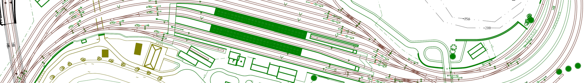
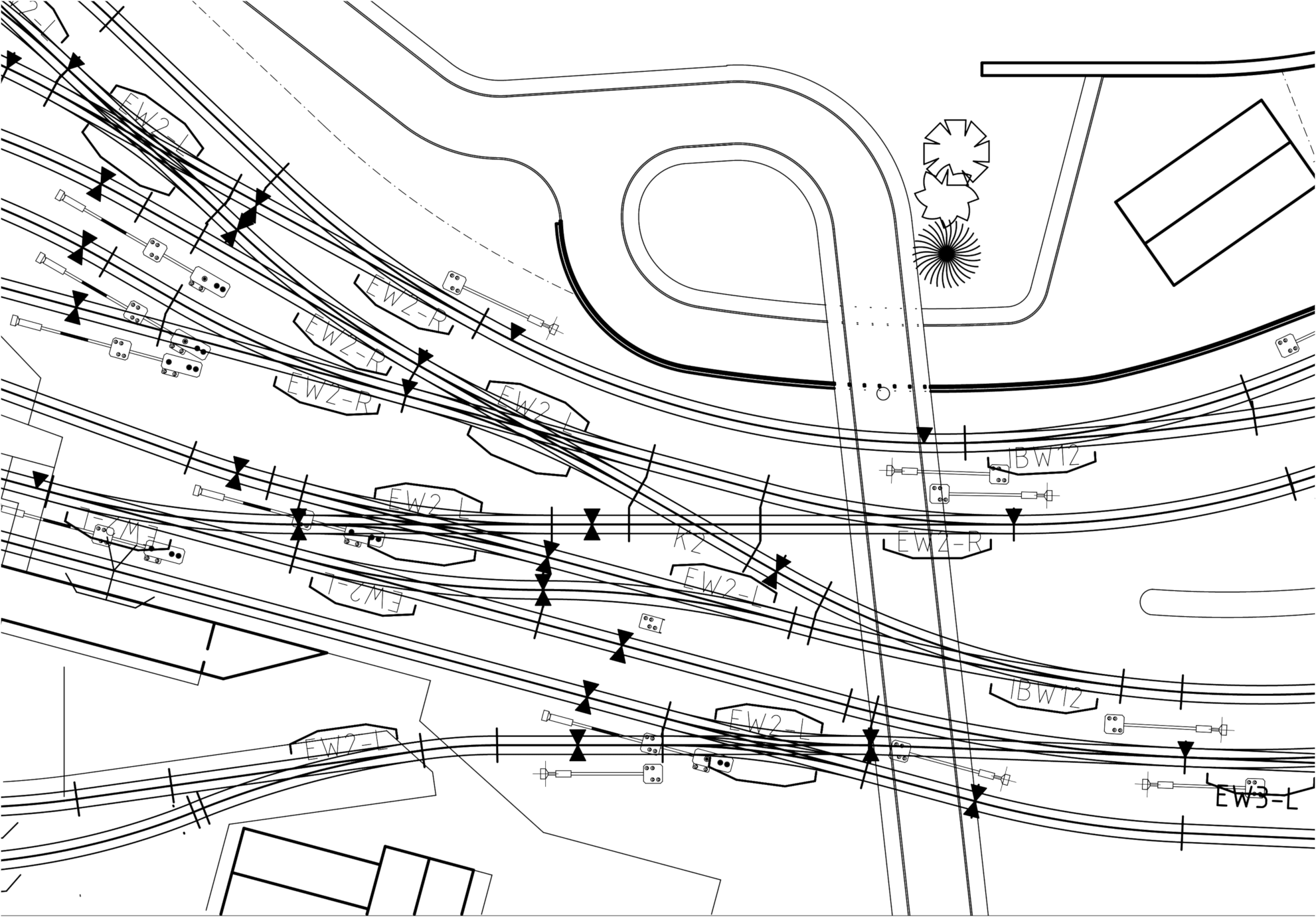
This approach was also suitable for the curved eastern entrance to Bf Schwarzach - St Veit station. The track to platform track 4 was assigned as the reference track, see the filled-in track in the drawing below. For the parallel track, a radius approximation was needed because of the geometric differences between switches in TT and the real world.
If the curve does not meet the above criteria then the formula is:
where: rTT = radius in TT rw = radius in the real world rm = minimum allowed radius in TT rs = smallest radius real world
If the minimum allowable radius is entered, the formula becomes:
This is the correct method for the western entrance of Schwarzach - St Veit station, but even here approximation is needed in some cases.
Track distance
The goal is to bring the distance between the tracks as close to the real world as possible. But I wanted to use Tillig's Advanced Track, because it is reasonably priced, but more importantly, it has flexible turnouts that are needed for the entrances of the Schwarzach - St. Veit station. Tillig's Advanced Track has a geometry based on a track spacing of 43 mm. This does not correspond to NEM 112, which deals with this subject, nor to real world dimensions when converted to TT scale. However, in the real world when there is not enough space to place turnouts and crossings, a track spacing of 5 m is required. This is 41.7 mm in TT. This almost matches the standard spacing of Tillig's Advanced Track.
Consistent similarity is achieved 43 mm is used as a reference, i.e.:
The largest value of the calculated track spacing dTT and the values in the NEM 112 provide sufficient clearance between vehicles on adjacent tracks.
Track distance visible open lines
The distance between visible non-station tracks including curves is as follows.
Object
Property
TT track plan
Track with a radius of 800 mm ≤ r ≤ infinity
Centre spacing
34 mm
Track with a radius of 700 ≤ r < 800 mm
Centre spacing
35 mm
Track with a radius of 600 ≤ r < 700 mm
Centre spacing
36 mm
Track with a radius of 550 ≤ r < 600 mm
Centre spacing
37 mm
Track with a radius of 540 ≤ r < 550 mm
Centre spacing
38 mm
Note that the minimum curve radius for branch lines is 540 mm and for main lines 631 mm.
Hidden track spacing
The distance of hidden tracks is the standard spacing of Tillig's Advanced Track.
Object
Property
TT track plan
Track with a radius of 350 mm ≤ r < infinity
Centre spacing
43 mm
Rangeerspoorafstand hoofdstations
The equivalent spacing for shunting and hidden tracks in TT scale is 43 mm. In the real world the spacing is 5 m.
Object
Property
TT track plan
Track with a radius of 631 mm ≤ r < infinity
Centre spacing
43 mm
Tracks on both sides of main station platforms
The track spacing between the tracks on either side of the platforms in main stations is derived from a real world track spacing of 10.5 m. The fromule for equivalent track spacing in TT scale, taking into account that the equivalent track spacing for shunting in the real world is 5 m and the standard geometric track spacing of 43 mm in TT scale, is:
Note that this is equal to the track spacing according to NEM 112 times 2.
Object
Property
TT track plan
Track with a radius of 631 mm ≤ r < infinity
Centre spacing
90 mm
Tracks on both sides of branch station platforms
The track spacing between the tracks on either side of the platforms in station at branch lines is derived from a real world track spacing of 6.5 m. The equivalent track spacing in TT scale, taking into account that the equivalent track spacing for shunting and parking in the real world is 5 m and the standard geometric track spacing of 43 mm in TT scale.
Note that this is equal to the track spacing according to NEM 112 times 1.5.
Object
Property
TT track plan
Platform tracks branch lines
Centre spacing
57 mm
Spacing main tracks in stations
The distance between straight tracks between platforms and other main tracks in stations is derived from an actual distance of 4.5 m. The equivalent distance in TT scale is 39 mm. This is also according to NEM 112.
Object
Property
TT track plan
Track with a radius of 700 mm ≤ r < infinity
Centre spacing
39 mm
Track with a radius of 600 ≤ r < 700 mm
Centre spacing
40 mm
Track with a radius of 550 ≤ r < 600 mm
Centre spacing
41 mm
Track with a radius of 540 ≤ r < 550 mm
Centre spacing
42 mm
Note that the minimum allowable radius for tracks of main lines in stations is 631 mm and for branch lines is 540 mm.
Type of tracks
Richtlijnen voor het merk, type en de geometrie van rails.
Tillig's Advanced Track rails and flexible or straight sleeper strips are used and must be assembled. Standard straight or curved rails are therefore not used. Turnouts too are mostly composed of loose parts and in other cases ready-made. Only new silver rails are being fitted because loose rails are not available oxidised.
Note - The prices are recommended retail prices and are updated on 24 May 2024.
Flex track
The flexible track is composed of the following parts.
Article
Length
Article No.
Price
Wood new silver flex track
664 mm
Tillig 83125
€ 8.00
Wood flex sleeper band
220 mm
Tillig 83025
€ 1,30
Rails new silver
1 m
Tillig 83500
€ 2.20
Bumpers and decoupling tracks
These are special tracks and attributes which may be used.
Article
Length
Article No.
Price
Electric decoupling track with wooden sleepers
83,0 mm
Tillig 83201
€ 25.20
Bumper without track
N/A
Tillig 07950
€ 5.90
Bumper
41.5 mm
Tillig 83100
€ 8.00
Bumper D.I.Y kit
41.5 mm
Tillig 83440
€ 5.00
Straight turnouts
The turnouts used with one straight track.
Article
Length
Radius
Angle
Article No.
Price
Right turnout EW1
129.5 mm
353.0 mm
15º
Tillig 83321
€ 10.50
Right turnout EW1 D.I.Y. kit
129.5 mm
353.0 mm
15º
Tillig 83431
€ 8.90
Left turnout EW1
129.5 mm
353.0 mm
15º
Tillig 83322
€ 10.50
Left turnout EW1 D.I.Y. kit
129.5 mm
353.0 mm
15º
Tillig 83430
€ 8.90
Right turnouts EW2
166.0 mm
631.0 mm
15º
Tillig 83331
€ 15.50
Left turnouts EW2
166.0 mm
631.0 mm
15º
Tillig 83332
€ 15.50
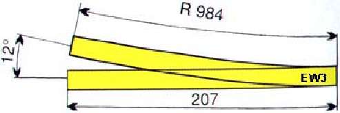
Right turnouts EW3
207.0 mm
984.0 mm
12º
Tillig 83341
€ 16.50
Left turnouts EW3
207.0 mm
984.0 mm
12º
Tillig 83342
€ 16.50
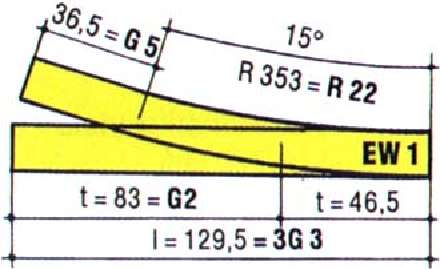
Geometry EW1 turnout Tillig's Advanced Track.
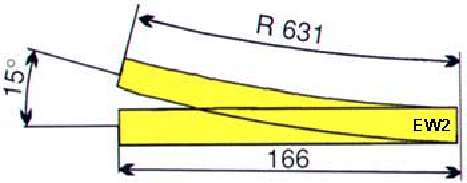
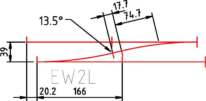
Geometry EW2 turnout Tillig's Advanced Track.
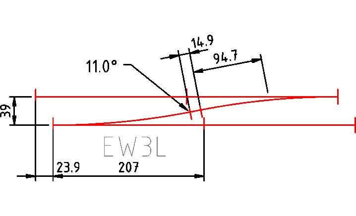
Geometry EW3 turnout Tillig's Advanced Track.
Crossings
One crossing is used at the western entrance to Schwarzach - St Veit station.
Article
Length
Angle
Article No.
Price
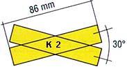
Crossings K2
86.0 mm
30°
Tillig 83170
€ 21.60
Geometrics K2 crossings Tillig's Advanced Track.
The K2 30° crossing Tillig's Advanced Track in the western entrance of Schwarzach - St Veit station is shown in the centre of the drawing below.
Single and double slip crossings
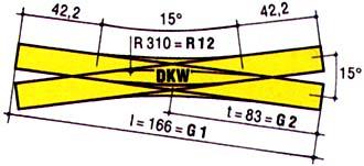
Single and double slip crossings are crossings with one and two sets of points, respectively. Crossings with two sets of points are what Tillig calls double slip points.
To enable 39 mm track spacing in stations, the following must be observed:
Remove 15.4 mm from the end of a double slip crossing (Tillig article No 83300) if used in combination with an EW2 15° turnout (Tillig article No 83331 or 83332), see figure below.
At the western entrance to Schwarzach - St Viet station is a Baeseler double slip crossing. On my TT model railway, however, a double slip crossing is used due to lack of space. Below you can see a photo of a Baeseler double slip crossing.
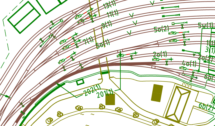
Flexible curved turnouts are used at the eastern entrance to Schwarzach - St Veit station for example, see below.
Application area turnouts
The radius and angle of the turnouts depend on the application.
Application
Guidelines
Suitable articles
Radius
Angle
On exposed open lines and high-speed hidden turnouts
±984 mm
12°
Tillig EW3
Tillig BW 12º
In exposed stations
±631 mm
15°
Tillig EW2
Tillig BW 15º
At hidden open lines and the shadow station
±353 mm
15°
Tillig EW1
Turnout calculations
This chapter deals with the calculations for the geometry of turnouts needed before you assemble them in the layout.
flexible turnout geometry
Guidelines to calculate the geometry of flexible turnouts.
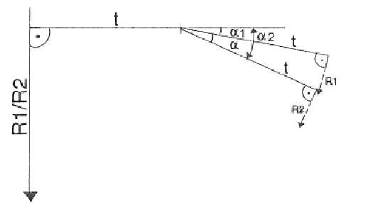
Use the formula to calculate curves and angles:
the angle of the main track curve:
the angle of the diverging curve:
the radius of the diverging curve:
where:
r1= the radius main track curve. α1= the angle of the main track curve:
for outside curved turnout: negative
for straight turnouts: 0
for inside curved turnouts: positive
r2= the radius of the diverging track curve: α2= the angle of the diverging track curve: α= the angle of the flexible turnout (either 15° or 12°) T = the tangent (83.1 mm for 15° or 103.4 mm for 12° flexible turnouts)
To enable 39 mm track spacing in stations, the following must be observed for crossovers with straight and flexible turnouts:
remove 1.5° from the diverging curve of the turnouts IBW 15º and EW2
remove 1° from the diverging curve of the turnouts IBW 12º and EW3.
Formula to calculate the piece of track from turnouts between at crossovers :
first calculate the tangent T of the turnout:
then calculate the spacing of the track at end of the turnout d1 [mm]:
next calculate the distance between the curved tracks of the two turnouts d2 [mm]:
length of the straight piece of track between the opposite turnouts l:
where:
r = the radius main track curve α = the angle of the curve (e.g. 12°) d = distance between parallel tracks
Curve transition
This section provides guidelines for calculating the transition from straight to curved track.
Easements
Easements are transitional curves between:
reverse curves
a radial curve and a straight track.
Transition of curves is applied on lines with speeds > 40 km/h, e.g.:
open lines
main tracks in station and yards
The method of applying a displacement of 6 mm is adopted as stated for TT scale in the NEM 113.
The length of the easement is determined by:
where:
L = length of the easement f = displacement of the straight track and the original location of the start of the curve R = radius of the curve
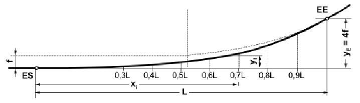
For construction, the intermediate points yi can be obtained as fractions of the final ordinate yE according to the table ‘Intervals offsets easement’.
After the values L and f are determined, the endpoints ES and EE of the easement can be obtained using the figure below and one of the following methods:
the extension of the line of the intended straight track and drawing a line parallel to the straight track with the position of yE = 4 f intersecting the circle. This intersection point is the end point EE of the easement
the starting point ES is determined by following the length L from the perpendicular of the intersection at EE back along the extension of the straight track.
where:
L = length of the easement f = displacement of straight track and original curve ES = easement starting point EE = easement end point yE = end ordinate yi = intermediate ordinate
The values in the figure above for the displacement fE at certain intervals of length L are shown in the diagram below.
Radius [mm]
Displacement on the y axis [mm]
0.3L
0.4L
0.5L
0.6L
0.7L
0.8L
0.9L
1.0L
0.03yE
0.06yE
0.125yE
0.21yE
0.33yE
0.49yE
0.72yE
1.0yE
0.7
1.4
3.0
5.0
7.9
11.8
17.3
24
Position displacement on x axis [mm]
353
67.6
90.2
112.7
135.3
157.8
180.4
202.9
225,5
396
71.6
95.5
119.4
143.3
167.2
191.0
214.9
238,8
439
75.4
100.6
125.7
150.9
176.0
201.1
226.3
251,4
482
79.0
105.4
131.7
158.1
184.4
210.8
237.1
263,5
525
82.5
110.0
137.5
165.0
192.5
220.0
247.5
275,0
568
85.8
114.4
143.0
171.6
200.2
228.8
257.4
286,0
611
89.0
118.6
148.3
178.0
207.6
237.3
267.0
296,6
654
92.1
122.8
153.4
184.1
214.8
245.5
276.2
306,9
697
95.0
126.7
158.4
190.1
221.8
253.4
285.1
316,8
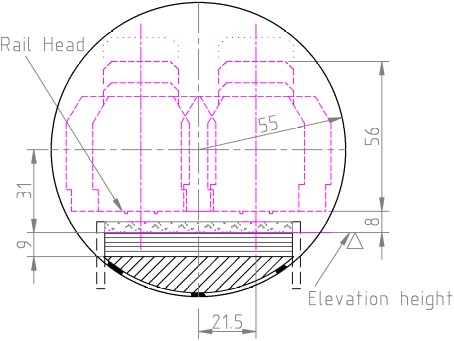
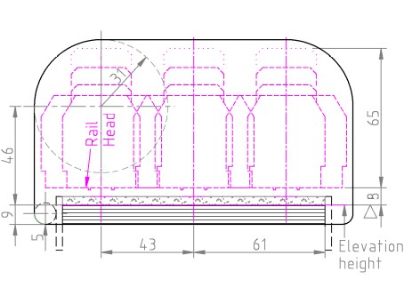
Headroom above rails
For tracks, a clearance of 48 mm is required between the top of the rail and the bottom of the overhead contact line. However, for shadow track without catenary but with the pantograph raised, a clearance of 56 mm from the rail head is required. The table below gives the minimum distance between the heads of superimposed rails depending on the presence of an overhead contact line. A margin of 1.8 mm has been added.
Catenary
Distance heads rails
Including; 4.2 mm track,
4 mm ballast and
9 mm base plate
Catenary strip 3 mm
In tunnels
70 mm
None and pantograph up
With hidden track
75 mm
Track slopes
General
The formula for the length l of a piece of track given the slope in promile is:
The formula for the elevation difference h of a track given its length and slope in pro-miles is:
Maximum slope
The gradient of the Tauernbahn is ≤ 35 ‰. The slope for my TT model railway is shown in the table below. The slopes are steeper than on the Tauernbahn because there is no room for the longer slope.
Object
Slope
Main lines
≤ 25 ‰ (1:40)
Branch lines
≤ 33 ‰ (1:30)
Helices
For tracks without catenary but with trains with pantographs up, the diameter d of the spiral is calculated using the formula:
Some examples based on the slope of the track:
Slope
Diameter helix
35 ‰
≥ 682 mm
33 ‰
≥ 723 mm
25 ‰
≥ 955 mm
Catenary
The guidelines for mast placement for overhead line electrification equipment for my TT model layout are as follows.
Masts straight tracks
The distance between masts along straight tracks is ≤ 326 mm.
Masts curved tracks
The formula used to calculate the maximum distance dm between masts at curved tracks is:
where: r = the radius of the curved track.
The maximum angle αm between two poles is calculated with:
where: r = the radius of the curved track.
Mast Distance from track
The distance between the centre of the mast and the centre of the track is at:
Cantilever masts: 24 mm
Masts for cross span assembly: 30 mm
Modules
Guidelines for the design and construction of the separable modules.
The modules are a sturdy, and as light as possible, support structure for my model railway. It is constructed from self-supporting ribs of 12 mm plywood. The support structure consists of 3 modules that can be detached for transport in case of moving.
The base plates to support the rails are of 9 mm plywood with 4 mm side panels in some places to prevent sagging.
The hidden tracks go through holes in the ribs. For ease of cutting, the holes are round and can be drilled with a circle drill, see below.
This method is only possible with two parallel tracks and if there is enough wood to drill the holes in without weakening the ribs. In all other situations, the hole is made as shown below.